FCTN-RLY4-315 Linx Technologies Inc, FCTN-RLY4-315 Datasheet - Page 2
FCTN-RLY4-315
Manufacturer Part Number
FCTN-RLY4-315
Description
RF Modules & Development Tools 4 Relay Receiver Module 315MHz
Manufacturer
Linx Technologies Inc
Datasheet
1.FCTN-RLY4-418.pdf
(7 pages)
Specifications of FCTN-RLY4-315
Board Size
146.7 mm x 81.3 mm x 45 mm
Minimum Operating Temperature
- 40 C
Supply Voltage (min)
5 V
Product
RF Modules
Maximum Frequency
315 MHz
Supply Voltage (max)
16 V
Supply Current
12 mA to 170 mA
Maximum Operating Temperature
+ 85 C
Lead Free Status / RoHS Status
Lead free / RoHS Compliant


Notes
1. Characterized, but not tested.
2. For BER of 10
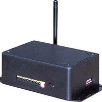
RELAY FUNCTION MODULE FEATURES
1. Antenna
2. DC Power Connector (5 to 16VDC)
3. “Quick-Connect” Alternate DC Input
4. Switched Device Connectors
5. Address Selector DIP Switches
Page 2
ELECTRICAL SPECIFICATIONS
Parameter
POWER SUPPLY
Operating Voltage
Supply Current
RECEIVER SECTION
Receive Frequency Range
Center Frequency Accuracy
Receiver Sensitivity
RELAY CHARACTERISTICS
Arrangement
Switched Power
Relay Switching Voltage
Switched Device Current
Operate Time
Release Time
Life Expectancy
Contact Dielectric Strength
ENVIRONMENTAL
Operating Temperature Range
Storage Temperature Range
FCTN-RLY4-315
FCTN-RLY4-418
FCTN-RLY4-433
Mechanical
Electrical
(at sea level for 1 minute)
-5
at 1,200bps.
Designation
V
I
F
CC
–
–
–
–
–
–
–
–
–
–
–
–
–
–
–
–
CC
C
Min.
-106
12.0
5.0
-50
0.0
0.0
0.6
-40
-45
–
–
–
–
–
–
–
3000Vrms contact-to-coil
750Vrms between open
30VDC or 250VAC
1x10
Figure 2: Relay Module Features
20 million
Typical
433.92
SPST
-112
315
418
6.0
3.0
-5
–
–
–
–
–
–
–
–
–
–
@ 5A
4
170.0
250.0
Max.
-118
1250
16.0
30.0
+50
150
+85
+85
5.0
–
–
–
–
–
3
2
cycles
Units
watts
VDC
VDC
MHz
MHz
MHz
dBm
VAC
1
kHz
mA
mS
mS
VA
°
°
A
C
C
Notes
5
–
1
–
–
–
–
2
–
–
–
–
–
–
–
–
1
1
THEORY OF OPERATION
POWER SUPPLY CONSIDERATIONS
SETTING THE MODULE ADDRESS
The FCTN-RLY4-*** module combines
the popular Linx LR Series receiver
with a decoder IC and four relays that
are capable of switching a variety of AC
or DC loads. The Relay Function
Module is designed to receive a
wireless signal transmitted from a
compatible Linx RF module or pre-
certified
transmitted data is received, the data is
presented to the decoder. The decoder
detects the logic states of the DIP
switch address lines, and if they match
the address settings of the encoder, the
decoder’s outputs are set to replicate
the state of the encoder’s data lines.
The relay outputs are then latched on
or off. If momentary operation is
desired, jumper pads J2 through J5 can
be bridged. Figure 3 displays the
location of the pads. Each jumper
corresponds to a relay as shown.
The module should be powered from a DC source that is free of noise and high
ripple. The best results are normally obtained using a battery or high quality AC
wall adapter capable of providing the supply currents indicated in the Electrical
Specifications section. Two supply connection options are provided: black
(ground) and red (+) quick-connect terminals or a barrel jack (for a 5.5mm plug,
tip 7 to 16VDC, shell ground). Only one connection should be used at a time and
polarity should be observed.
The Relay Function Module provides
a total of 256 unique addreses to
avoid contention with other units or
to
Address selection is made via eight
externally accessible DIP switches
as shown in the adjacent figure.
If the switch is on, the address line is
connected to ground, otherwise it is
floating. The transmitter’s address
must match exactly in order for the
units to communicate. Application
Note AN-00300 describes in detail how to set the address to match any of the
transmitters offered by Linx. This application note can be found in the Support
section of the Linx website, www.linxtechnologies.com.
create
OEM
unique
transmitter.
relationships.
When
Figure 4: Address DIP Switches
Figure 3: Jumper Pad Locations
Jumper
Relay
J2
1
J3
2
J5
3
Jumper Pads
Page 3
J4
4
Related parts for FCTN-RLY4-315
Image
Part Number
Description
Manufacturer
Datasheet
Request
R

Part Number:
Description:
MODULE 4 RELAY RECEIVER 418MHZ
Manufacturer:
Linx Technologies Inc
Datasheet:

Part Number:
Description:
MODULE 4 RELAY RECEIVER 433MHZ
Manufacturer:
Linx Technologies Inc
Datasheet:

Part Number:
Description:
MODULE 4 RELAY RECEIVER 315MHZ
Manufacturer:
Linx Technologies Inc
Datasheet:

Part Number:
Description:
MODULE AC SWITCH RECEIVER 433MHZ
Manufacturer:
Linx Technologies Inc
Datasheet:

Part Number:
Description:
MODULE AC SWITCH RECEIVER 315MHZ
Manufacturer:
Linx Technologies Inc
Datasheet:

Part Number:
Description:
MODULE AC SWITCH RECEIVER 418MHZ
Manufacturer:
Linx Technologies Inc
Datasheet:

Part Number:
Description:
MODULE 4 POS RECEIVER 418MHZ
Manufacturer:
Linx Technologies Inc
Datasheet:

Part Number:
Description:
MODULE RECEIVER DECODER 315MHZ
Manufacturer:
Linx Technologies Inc
Datasheet:
Part Number:
Description:
MODULE RECEIVER DECODER 418MHZ
Manufacturer:
Linx Technologies Inc
Datasheet:
Part Number:
Description:
MODULE RECEIVER DECODER 433MHZ
Manufacturer:
Linx Technologies Inc
Datasheet:

Part Number:
Description:
MODULE USB LOW SPEED
Manufacturer:
Linx Technologies Inc
Datasheet:

Part Number:
Description:
IC TRANSCODER MT BI-DIR 20-SSOP
Manufacturer:
Linx Technologies Inc
Datasheet:

Part Number:
Description:
IC ENCODER LOW SECURITY 8DIP
Manufacturer:
Linx Technologies Inc
Datasheet:

Part Number:
Description:
IC DECODER MS SERIES 20-SSOP
Manufacturer:
Linx Technologies Inc
Datasheet:
Part Number:
Description:
IC ENCODER MS SERIES 20-SSOP
Manufacturer:
Linx Technologies Inc
Datasheet: