AD9778ABSVZ Analog Devices Inc, AD9778ABSVZ Datasheet - Page 29
AD9778ABSVZ
Manufacturer Part Number
AD9778ABSVZ
Description
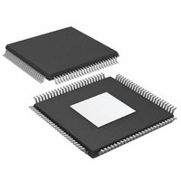
IC,D/A CONVERTER,DUAL,14-BIT,CMOS,TQFP,100PIN
Manufacturer
Analog Devices Inc
Specifications of AD9778ABSVZ
Number Of Bits
14
Data Interface
Parallel
Number Of Converters
2
Voltage Supply Source
Analog and Digital
Power Dissipation (max)
300mW
Operating Temperature
-40°C ~ 85°C
Mounting Type
Surface Mount
Package / Case
100-TQFP Exposed Pad, 100-eTQFP, 100-HTQFP, 100-VQFP
Package
100TQFP EP
Resolution
14 Bit
Conversion Rate
1 GSPS
Architecture
Interpolation Filter
Digital Interface Type
Parallel
Number Of Outputs Per Chip
2
Output Type
Current
Full Scale Error
±2(Typ) %FSR
Integral Nonlinearity Error
±1.5(Typ) LSB
Lead Free Status / RoHS Status
Lead free / RoHS Compliant
For Use With
AD9778A-EBZ - BOARD EVALUATION AD9778A
Settling Time
-
Lead Free Status / RoHS Status
Lead free / RoHS Compliant
Available stocks
Company
Part Number
Manufacturer
Quantity
Price
Company:

Part Number:
AD9778ABSVZ
Manufacturer:
Analog Devices Inc
Quantity:
135
Company:
Part Number:
AD9778ABSVZ
Manufacturer:
Analog Devices Inc
Quantity:
10 000
Part Number:
AD9778ABSVZ
Manufacturer:
ADI/亚德诺
Quantity:
20 000
Company:
Part Number:
AD9778ABSVZRL
Manufacturer:
Analog Devices Inc
Quantity:
10 000


Table 14. 3-Wire Interface Register Description
Register Name
Comm
Digital Control
Register
Address
0x00
0x00
0x00
0x00
0x00
0x00
0x01
0x01
0x01
0x01
0x02
0x02
0x02
0x02
0x02
0x02
0x02
0x02
Bits
7
6
5
4
3
1
7:6
5:2
1
0
7
6
5
4
3
2
1
0
Parameter
SDIO bidirectional
LSB/MSB first
Software reset
Power-down mode
Auto power-down enable
PLL lock indicator
(read only)
Interpolation Factor[1:0]
Filter Modulation Mode[3:0]
DATACLK Delay[4]
Zero stuffing enable
Data format
Single port
Real mode
DATACLK delay enable
Inverse sinc enable
DATACLK invert
TxEnable invert
Q first
Rev. B | Page 29 of 56
Function
0: use SDIO pin as input data only.
1: use SDIO as both input and output data.
0: first bit of serial data is MSB of data byte.
1: first bit of serial data is LSB of data byte.
Bit must be written with a 1 and then 0 to soft reset
the 3-wire interface register map.
0: all circuitry is active.
1: disable all digital and analog circuitry, only
3-wire interface port is active.
Controls auto power-down mode. See the Power-
Down and Sleep Modes section.
0: PLL is not locked.
1: PLL is locked.
00: 1× interpolation.
01: 2× interpolation.
10: 4× interpolation.
11: 8× interpolation.
See Table 19 for filter modes.
Sets MSB of delay of REFCLK input to DATACLK
output.
0: zero stuffing off.
1: zero stuffing on.
0: twos compliment.
1: unsigned binary.
0: both P1D and P2D data ports enabled.
1: data for both DACs received on P1D data port.
0: enable Q path for signal processing.
1: disable Q path data (internal Q channel clocks
disabled, I and Q modulators disabled).
Enables the DATACLK delay feature. More details
on this feature are shown in the Optimizing the
Data Input Timing section.
0: inverse sinc filter disabled.
1: inverse sinc filter enabled.
0: output DATACLK same phase as internal data
sampling clock, DCLK_SMP signal.
1: output DATACLK opposite phase as internal data
sampling clock, DCLK_SMP signal.
Inverts the polarity of Pin 39, the TXENABLE input
pin (also functions as IQSELECT).
0: in interleaved mode, the I data precedes the
Q data on the input port.
1: in interleaved mode, the Q data precedes the
I data on the input port.
AD9776A/AD9778A/AD9779A
Default
0
0
0
0
00
0000
0
0
0
0
0
0
0
0
Related parts for AD9778ABSVZ
Image
Part Number
Description
Manufacturer
Datasheet
Request
R

Part Number:
Description:
Dual 16B, 1.0 GSPS TxDAC
Manufacturer:
Analog Devices Inc
Datasheet:
Part Number:
Description:
BOARD EVALUATION FOR AD9778
Manufacturer:
Analog Devices Inc
Datasheet:

Part Number:
Description:
±1.7g Dual-Axis IMEMS Accelerometer Evaluation Board
Manufacturer:
Analog Devices Inc
Datasheet:
Part Number:
Description:
Inertial Sensor Evaluation System
Manufacturer:
Analog Devices Inc
Datasheet:
Part Number:
Description:
Manufacturer:
Analog Devices Inc
Datasheet:
Part Number:
Description:
Manufacturer:
Analog Devices Inc
Datasheet:
Part Number:
Description:
Manufacturer:
Analog Devices Inc
Datasheet:
Part Number:
Description:
Manufacturer:
Analog Devices Inc
Datasheet:
Part Number:
Description:
Manufacturer:
Analog Devices Inc
Datasheet:
Part Number:
Description:
Manufacturer:
Analog Devices Inc
Datasheet:
Part Number:
Description:
Manufacturer:
Analog Devices Inc
Datasheet:
Part Number:
Description:
Manufacturer:
Analog Devices Inc
Datasheet: