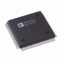
AD9887AKSZ-140 Analog Devices Inc, AD9887AKSZ-140 Datasheet - Page 42

AD9887AKSZ-140
Manufacturer Part Number
AD9887AKSZ-140
Description
IC,TV/VIDEO CIRCUIT,Video Digitizer,CMOS,QFP,160PIN,PLASTIC
Manufacturer
Analog Devices Inc
Datasheet
1.AD9887AKSZ-140.pdf
(52 pages)
Specifications of AD9887AKSZ-140
Applications
Graphic Cards, VGA Interfaces
Interface
Analog and Digital
Voltage - Supply
3.15 V ~ 3.45 V
Package / Case
160-MQFP, 160-PQFP
Mounting Type
Surface Mount
Lead Free Status / RoHS Status
Lead free / RoHS Compliant
Available stocks
Company
Part Number
Manufacturer
Quantity
Price
Company:
Part Number:
AD9887AKSZ-140
Manufacturer:
MAX
Quantity:
59
Company:
Part Number:
AD9887AKSZ-140
Manufacturer:
ADI
Quantity:
364
Company:
Part Number:
AD9887AKSZ-140
Manufacturer:
Analog Devices Inc
Quantity:
10 000
Part Number:
AD9887AKSZ-140
Manufacturer:
ADI/亚德诺
Quantity:
20 000
AD9887A
0x12 0
Table 44. Power-Down Settings
Select
0
1
Digital Control
0x13 7:0
Control Bits
0x14 2
Table 45. Scan Enable Settings
Scan Enable
0
1
0x14 1
Table 46. COAST Input Polarity Override Settings
Override Bit
0
1
This bit can be used to fully power down both interfaces
of the chip. See the Power Management section for
details on which blocks are actually powered down. Note
that the chip is unable to detect incoming activity while
fully powered down.
This register is used to set the responsiveness of the sync
separator. It sets the number of 5 MHz clock pulses the
sync separator counts before toggling high or low. It works
like a low-pass filter to ignore Hsync pulses in order to
extract the Vsync signal. This register should be set to a
number greater than the maximum Hsync pulse width.
The default for this register is 32.
This register is used to enable the scan function. When
this function is enabled, data can be loaded into the
AD9887A outputs serially. The scan function utilizes
three pins: SCAN
are described in the Scan Function section.
The default for scan enable is 0 (disabled).
This register is used to override the internal circuitry
that determines the polarity of the coast signal going
into the PLL.
The default for coast polarity override is 0.
The default for this register is 1.
PWRDN
Sync Separator Threshold
Scan Enable
COAST Input Polarity Override
Result
Coast polarity determined by chip
Coast polarity determined by user
Result
Power down
Normal operation
Result
Scan function disabled
Scan function enabled
IN
, SCAN
OUT
, and SCAN
CLK
. These pins
Rev. B | Page 42 of 52
0x14 0
Table 47. HSYNC Input Polarity Override Setting
Override Bit
0
1
0x15 7
Table 48. Detected HSYNC Input Polarity Status
Status
0
1
0x15 6
Table 49. Detected Vsync Input Polarity Status
Status
0
1
0x15 5
Table 50. Detected COAST Input Polarity Status
Status
0
1
0x16 7–3
This register is used to override the internal circuitry
that determines the polarity of the Hsync signal going
into the PLL.
The default for HSYNC input polarity override is 0.
This bit reports the status of the HSYNC input polarity
detection circuit. It can be used to determine the polarity
of the HSYNC input. The location of the detection
circuit is shown in the Figure 43.
This bit reports the status of the VSYNC output polarity
detection circuit. It can be used to determine the polarity
of the VSYNC input. The location of the detection
circuit is shown in the Figure 43.
This bit reports the status of the COAST input polarity
detection circuit. It can be used to determine the polarity
of the coast input. The location of the detection circuit is
shown in the Figure 43.
This register allows the comparator threshold of the
sync-on-green slicer to be adjusted. This register adjusts
the comparator threshold in 10 mV steps. A setting of 0
results in a 330 mV threshold; a setting of 31 results in a
10 mV threshold. The default setting is 23, which corre-
sponds to a threshold value of 70 mV.
HSYNC Input Polarity Override
HSYNC Input Polarity Status
VSYNC Output Polarity Status
COAST Input Polarity Status
Sync-on-Green Slicer Threshold
Result
HSYNC input polarity determined by chip
HSYNC input polarity determined by user
Result
Vsync input polarity is active low.
Vsync input polarity is active high.
Result
HSYNC input polarity is negative.
HSYNC input polarity is positive.
Result
Coast input polarity is negative.
Coast input polarity is positive.


