ADXL345BCCZ-RL Analog Devices Inc, ADXL345BCCZ-RL Datasheet - Page 36
ADXL345BCCZ-RL
Manufacturer Part Number
ADXL345BCCZ-RL
Description
Digital Output Three-Axis Accel 4K RL
Manufacturer
Analog Devices Inc
Series
iMEMS®r
Datasheet
1.EVAL-ADXL345Z.pdf
(40 pages)
Specifications of ADXL345BCCZ-RL
Design Resources
Sensing Low-g Acceleration Using ADXL345 Digital Accelerometer Connected to ADuC7024 (CN0133)
Axis
X, Y, Z
Acceleration Range
±2g, 4g, 8g, 16g
Sensitivity
256LSB/g, 128LSB/g, 64LSB/g, 32LSB/g
Voltage - Supply
2 V ~ 3.6 V
Output Type
Digital
Bandwidth
6.25Hz ~ 3.2kHz Selectable
Interface
I²C, SPI
Mounting Type
Surface Mount
Package / Case
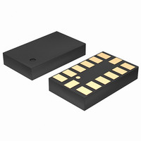
14-LGA
Package Type
LGA
Operating Supply Voltage (typ)
2.5V
Operating Supply Voltage (max)
3.6V
Operating Temperature (min)
-40C
Operating Temperature (max)
85C
Operating Temperature Classification
Industrial
Product Depth (mm)
3mm
Product Length (mm)
5mm
Mounting
Surface Mount
Pin Count
14
Lead Free Status / RoHS Status
Lead free / RoHS Compliant
Lead Free Status / RoHS Status
Lead free / RoHS Compliant
Other names
ADXL345BCCZ-RLTR
Available stocks
Company
Part Number
Manufacturer
Quantity
Price
Company:

Part Number:
ADXL345BCCZ-RL7
Manufacturer:
POWER
Quantity:
14 300


ADXL345
LAYOUT AND DESIGN RECOMMENDATIONS
Figure 58 shows the recommended printed wiring board land pattern. Figure 59 and Table 24 provide details about the recommended
soldering profile.
Table 24. Recommended Soldering Profile
Profile Feature
Average Ramp Rate from Liquid Temperature (T
Preheat
T
Liquid Temperature (T
Time Maintained Above T
Peak Temperature (T
Time of Actual T
Ramp-Down Rate
Time 25°C to Peak Temperature
1
2
Based on JEDEC Standard J-STD-020D.1.
For best results, the soldering profile should be in accordance with the recommendations of the manufacturer of the solder paste used.
SMAX
Minimum Temperature (T
Maximum Temperature (T
Time from T
to T
L
Ramp-Up Rate
SMIN
P
− 5°C (t
to T
P
)
SMAX
L
)
L
P
(t
)
(t
L
S
)
SMIN
)
SMAX
Figure 58. Recommended Printed Wiring Board Land Pattern (Dimensions shown in millimeters)
)
)
T
T
P
L
T
SMIN
1, 2
T
5.3400
SMAX
L
) to Peak Temperature (T
3.0500
Figure 59. Recommended Soldering Profile
PREHEAT
t
25°C TO PEAK
t
S
Rev. B | Page 36 of 40
0.2500
RAMP-UP
3.3400
1.0500
TIME
P
)
RAMP-DOWN
1.1450
t
P
t
L
0.5500
0.2500
CRITICAL ZONE
Sn63/Pb37
3°C/sec maximum
100°C
150°C
60 sec to 120 sec
183°C
60 sec to 150 sec
240 + 0/−5°C
10 sec to 30 sec
3°C/sec maximum
6°C/sec maximum
6 minutes maximum
T
L
TO T
P
Condition
Pb-Free
3°C/sec maximum
150°C
200°C
60 sec to 180 sec
3°C/sec maximum
217°C
60 sec to 150 sec
260 + 0/−5°C
20 sec to 40 sec
6°C/sec maximum
8 minutes maximum
Related parts for ADXL345BCCZ-RL
Image
Part Number
Description
Manufacturer
Datasheet
Request
R

Part Number:
Description:
±1.7g Dual-Axis IMEMS Accelerometer Evaluation Board
Manufacturer:
Analog Devices Inc
Datasheet:

Part Number:
Description:
Inertial Sensor Evaluation System
Manufacturer:
Analog Devices Inc
Datasheet:
Part Number:
Description:
Manufacturer:
Analog Devices Inc
Datasheet:
Part Number:
Description:
Manufacturer:
Analog Devices Inc
Datasheet:
Part Number:
Description:
Manufacturer:
Analog Devices Inc
Datasheet:
Part Number:
Description:
Manufacturer:
Analog Devices Inc
Datasheet:
Part Number:
Description:
Manufacturer:
Analog Devices Inc
Datasheet:
Part Number:
Description:
Manufacturer:
Analog Devices Inc
Datasheet:
Part Number:
Description:
Manufacturer:
Analog Devices Inc
Datasheet:
Part Number:
Description:
Manufacturer:
Analog Devices Inc
Datasheet:
Part Number:
Description:
Manufacturer:
Analog Devices Inc
Datasheet:
Part Number:
Description:
Manufacturer:
Analog Devices Inc
Datasheet:
Part Number:
Description:
Manufacturer:
Analog Devices Inc
Datasheet: