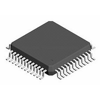
CS4299-JQZR Cirrus Logic Inc, CS4299-JQZR Datasheet - Page 3

CS4299-JQZR
Manufacturer Part Number
CS4299-JQZR
Description
IC AC97 Codec With SRC
Manufacturer
Cirrus Logic Inc
Series
SoundFusion™r
Type
Audio Codec '97r
Datasheet
1.CS4299-JQZ.pdf
(52 pages)
Specifications of CS4299-JQZR
Data Interface
Serial
Resolution (bits)
18 b, 20 b
Number Of Adcs / Dacs
1 / 1
Sigma Delta
Yes
Dynamic Range, Adcs / Dacs (db) Typ
85 / 87
Voltage - Supply, Analog
4.75 V ~ 5.25 V
Voltage - Supply, Digital
3.3 V ~ 5 V
Operating Temperature
0°C ~ 70°C
Mounting Type
Surface Mount
Package / Case
48-LQFP
No. Of Dacs
1
No. Of Input Channels
6
No. Of Output Channels
2
Adc / Dac Resolution
20bit
Adcs / Dacs Signal To Noise Ratio
70dB
Sampling Rate
48kSPS
Supply Voltage Range
3.135V To 3.465V, 4.75V To 5.25V
Lead Free Status / RoHS Status
Lead free / RoHS Compliant
Available stocks
Company
Part Number
Manufacturer
Quantity
Price
Company:
Part Number:
CS4299-JQZR
Manufacturer:
ON
Quantity:
2 245
Company:
Part Number:
CS4299-JQZR
Manufacturer:
Cirrus Logic Inc
Quantity:
10 000
DS319PP6
LIST OF FIGURES
5. POWER MANAGEMENT ................................................................................................. 32
Figure 1. Power Up Timing ....................................................................................................... 8
Figure 2. Codec Ready from Startup or Fault Condition ........................................................... 8
Figure 3. Clocks ........................................................................................................................ 8
Figure 4. Data Setup and Hold.................................................................................................. 9
Figure 5. PR4 Powerdown and Warm Reset ............................................................................ 9
Figure 6. Test Mode .................................................................................................................. 9
Figure 7. AC-link Connections ................................................................................................ 10
Figure 8. Mixer Diagram.......................................................................................................... 12
Figure 9. AC-link Input and Output Framing ........................................................................... 13
Figure 10. Line Input (Replicate for Video and Aux) ...............................................................35
6. ANALOG HARDWARE DESCRIPTION ......................................................................... 35
7. SONY/PHILIPS DIGITAL INTERFACE (S/PDIF) ............................................................39
8. GROUNDING AND LAYOUT ..........................................................................................39
9. PIN DESCRIPTIONS
10. PARAMETER AND TERM DEFINITIONS ....................................................................46
11. REFERENCE DESIGN .................................................................................................48
12. REFERENCES ..............................................................................................................49
13. PACKAGE DIMENSIONS .............................................................................................50
4.10 Stereo Analog Mixer Input Gain Registers (Index 10h - 18h) ................................. 24
4.11 Input Mux Select Register (Index 1Ah) ................................................................... 25
4.12 Record Gain Register (Index 1Ch) ......................................................................... 25
4.13 General Purpose Register (Index 20h) ................................................................... 26
4.14 3D Control Register (Index 22h) ............................................................................. 26
4.15 Powerdown Control/Status Register (Index 26h) ................................................... 27
4.16 Extended Audio ID Register (Index 28h) ................................................................ 28
4.17 PCM Front DAC Rate Register (Index 2Ch)
4.18 PCM L/R ADC Rate Register (Index 32h) .............................................................. 28
4.19 AC Mode Control Register (Index 5Eh) .................................................................. 29
4.20 Misc. Crystal Control Register (Index 60h) ............................................................. 29
4.21 S/PDIF Control Register (Index 68h) .....................................................................30
4.22 Vendor ID1 Register (Index 7Ch) ........................................................................... 31
4.23 Vendor ID2 Register (Index 7Eh) ........................................................................... 31
5.1 AC ’97 Reset Modes ................................................................................................ 32
5.2 Powerdown Controls ................................................................................................ 33
6.1 Analog Inputs ...........................................................................................................35
6.2 Analog Outputs ........................................................................................................37
6.3 Miscellaneous Analog Signals .................................................................................38
6.4 Power Supplies ........................................................................................................38
6.5 Reference Design ....................................................................................................38
5.1.1 Cold AC ‘97 Reset ....................................................................................... 32
5.1.2 Warm AC ’97 Reset ..................................................................................... 32
5.1.3 Register AC ’97 Reset ................................................................................. 32
6.1.4 Line-Level Inputs ........................................................................................35
6.1.5 CD Input .....................................................................................................35
6.1.6 Microphone Inputs ......................................................................................36
6.1.7 PC Beep Input ............................................................................................36
6.1.8 Phone Input ................................................................................................37
6.2.9 Stereo Outputs ...........................................................................................37
6.2.10 Mono Output .............................................................................................37
........................................................28
41
CS4299
CS4299
3
3


