EVAL-ADF7021-NDBZ5 Analog Devices Inc, EVAL-ADF7021-NDBZ5 Datasheet - Page 4
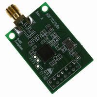
EVAL-ADF7021-NDBZ5
Manufacturer Part Number
EVAL-ADF7021-NDBZ5
Description
Matching Unpopulated
Manufacturer
Analog Devices Inc
Type
Transceiver, FSKr
Datasheet
1.ADF7021-NBCPZ-RL.pdf
(64 pages)
Specifications of EVAL-ADF7021-NDBZ5
Frequency
80MHz ~ 650MHz
Lead Free Status / RoHS Status
Lead free / RoHS Compliant
For Use With/related Products
ADF7021-N
Lead Free Status / Rohs Status
Supplier Unconfirmed


ADF7021-N
SPECIFICATIONS
V
All measurements are performed with the EVAL-ADF7021-NDBxx using the PN9 data sequence, unless otherwise noted.
RF AND PLL SPECIFICATIONS
Table 1.
Parameter
RF CHARACTERISTICS
PHASE-LOCKED LOOP (PLL)
REFERENCE INPUT
ADC PARAMETERS
1
2
3
4
5
6
7
The maximum usable PFD at a particular RF frequency is limited by the minimum N divide value.
VCO gain measured at a VCO tuning voltage of 0.7 V. The VCO gain varies across the tuning range of the VCO. The software package ADIsimPLL™ can be used to model this
variation.
This value can be used to calculate the in-band phase noise for any operating frequency. Use the following equation to calculate the in-band phase noise performance
as seen at the power amplifier (PA) output: −203 + 10 log(f
Guaranteed by design. Sample tested to ensure compliance.
A TCXO, VCXO, or OCXO can be used as an external oscillator.
Crystal start-up time is the time from chip enable (CE) being asserted to correct clock frequency on the CLKOUT pin.
Refer to the Reference Input section for details on using an external oscillator.
DD
Frequency Ranges (Direct Output)
Frequency Ranges (RF Divide-by-2 Mode)
Phase Frequency Detector (PFD) Frequency
Phase Noise (In-Band)
Phase Noise (Out-of-Band)
Normalized In-Band Phase Noise Floor
PLL Settling
Crystal Reference
External Oscillator
Crystal Start-Up Time
Input Level for External Oscillator
INL
DNL
VCO Gain
= 2.3 V to 3.6 V, GND = 0 V, T
868 MHz, Internal Inductor VCO
426 MHz, Internal Inductor VCO
426 MHz, External Inductor VCO
160 MHz, External Inductor VCO
868 MHz, Internal Inductor VCO
433 MHz, Internal Inductor VCO
426 MHz, External Inductor VCO
XTAL Bias = 20 μA
XTAL Bias = 35 μA
OSC1
OSC2
2
4
4, 5
6
A
7
= T
MIN
3
1
to T
Min
160
842
80
421
RF/256
3.625
3.625
MAX
PFD
, unless otherwise noted. Typical specifications are at V
) + 20 logN.
Typ
67
45
27
6
−97
−103
−95
−124
−203
40
0.930
0.438
0.8
CMOS levels
±0.4
±0.4
Rev. 0 | Page 4 of 64
Max
650
916
325
458
24
24
24
Unit
MHz
MHz
MHz
MHz
MHz/V
dBc/Hz
μs
MHz
MHz
ms
ms
V p-p
LSB
LSB
MHz
MHz/V
MHz/V
MHz/V
dBc/Hz
dBc/Hz
dBc/Hz
dBc/Hz
V
Test Conditions/Comments
See Table 9 for required VCO_BIAS and
VCO_ADJUST settings
External inductor VCO
Internal inductor VCO
External inductor VCO, RF divide-by-2 enabled
Internal inductor VCO, RF divide-by-2 enabled
VCO_ADJUST = 0, VCO_BIAS = 8
VCO_ADJUST = 0, VCO_BIAS = 8
VCO_ADJUST = 0, VCO_BIAS = 3
VCO_ADJUST = 0, VCO_BIAS = 2
10 kHz offset, PA = 10 dBm, V
PFD = 19.68 MHz, VCO_BIAS = 8
10 kHz offset, PA = 10 dBm, V
PFD = 19.68 MHz, VCO_BIAS = 8
10 kHz offset, PA = 10 dBm, V
PFD = 9.84 MHz, VCO_BIAS = 3
1 MHz offset, f
V
Measured for a 10 MHz frequency step to within
5 ppm accuracy, PFD = 19.68 MHz, loop bandwidth
(LBW) = 100 kHz
10 MHz XTAL, 33 pF load capacitors, V
10 MHz XTAL, 33 pF load capacitors, V
Clipped sine wave
V
V
DD
DD
DD
= 3.0 V, PFD = 19.68 MHz, VCO_BIAS = 8
= 2.3 V to 3.6 V, T
= 2.3 V to 3.6 V, T
RF
= 433 MHz, PA = 10 dBm,
DD
A
A
= 3 V, T
= 25°C
= 25°C
A
DD
DD
DD
= 25°C.
= 3.0 V,
= 3.0 V,
= 3.0 V,
DD
DD
= 3.0 V
= 3.0 V
Related parts for EVAL-ADF7021-NDBZ5
Image
Part Number
Description
Manufacturer
Datasheet
Request
R

Part Number:
Description:
±1.7g Dual-Axis IMEMS Accelerometer Evaluation Board
Manufacturer:
Analog Devices Inc
Datasheet:

Part Number:
Description:
Inertial Sensor Evaluation System
Manufacturer:
Analog Devices Inc
Datasheet:
Part Number:
Description:
Manufacturer:
Analog Devices Inc
Datasheet:
Part Number:
Description:
Manufacturer:
Analog Devices Inc
Datasheet:
Part Number:
Description:
Manufacturer:
Analog Devices Inc
Datasheet:
Part Number:
Description:
Manufacturer:
Analog Devices Inc
Datasheet:
Part Number:
Description:
Manufacturer:
Analog Devices Inc
Datasheet:
Part Number:
Description:
Manufacturer:
Analog Devices Inc
Datasheet:
Part Number:
Description:
Manufacturer:
Analog Devices Inc
Datasheet:
Part Number:
Description:
Manufacturer:
Analog Devices Inc
Datasheet:
Part Number:
Description:
Manufacturer:
Analog Devices Inc
Datasheet:
Part Number:
Description:
Manufacturer:
Analog Devices Inc
Datasheet:
Part Number:
Description:
Manufacturer:
Analog Devices Inc
Datasheet: