MT9M413C36STM Aptina LLC, MT9M413C36STM Datasheet - Page 7
MT9M413C36STM
Manufacturer Part Number
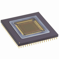
MT9M413C36STM
Description
SENSOR IMAGE MONO CMOS 280-PGA
Manufacturer
Aptina LLC
Type
CMOS Imagingr
Specifications of MT9M413C36STM
Pixel Size
12µm x 12µm
Active Pixel Array
1280H x 1024V
Frames Per Second
500
Voltage - Supply
3.3V
Package / Case
280-PGA
Sensor Image Color Type
Monochrome
Sensor Image Size
1280x1024Pixels
Operating Supply Voltage (min)
3V
Operating Supply Voltage (max)
3.6V
Operating Temp Range
-5C to 60C
Package Type
CPGA
Operating Temperature Classification
Commercial
Mounting
Through Hole
Pin Count
280
Lead Free Status / RoHS Status
Contains lead / RoHS non-compliant
Other names
557-1153


LD_SHFT_N
register to the output register (1280 x 10-bit) and gates
the power to the sense amplifiers. The first data (col-
umns 1-10) are available for output at the third rising
edge of SYSCLK after LD_SHFT_N is pulled low. May
be enabled simultaneously with or after the falling
edge of ROW_DONE_N. Must remain low the entire
time the data is being read out.
DATA_READ_EN_N
the output register (1280 x 10-bit) to the ten, 10-bit
output ports. May be initiated simultaneously with or
after LD_SHFT_N is selected. Minimum width is one
clock cycle.
09005aef806807ca
MT9M413C36STC.fm - Ver. 3.0 1/04 EN
This signal transfers the digitized data from the ADC
This signal is used to enable the data output from
ROW_ADDR [0:9]
ROW_ADDR [0:9]
DATA_READ_EN_N
DATA_READ_EN_N
ROW_DONE_N
ROW_DONE_N
ROW_STRT_N
ROW_STRT_N
SYSCLK
SYSCLK
PG_N
PG_N
LD_SHFT_N
LD_SHFT_N
DATA [0:99]
DATA [0:99]
PG2
PG2
PG1
PG1
TX_N
TX_N
XXX
XXX
0 1
0 1
Figure 6: Timing Diagram For One Row
2
2
1
1
0 1 2 3 4 5
0 1 2 3 4 5
-3 nsec SKEW
-3 nsec
ROW VA LID
ROW VA LID
1.3-MEGAPIXEL CMOS ACTIVE-PIXEL
7
Table 2:
Output Register
of a row to be performed while the digital data from
the previous operation is being read out of the sensor.
A new pixel readout and conversion cycle can be
started two clock cycles after DATA_READ_EN_N is
pulled low.
Port 1
Port 2
Port 3
Port 4
Port 5
Port 6
Port 7
Port 8
Port 9
Port 10
The use of an output register allows the processing
Micron Technology, Inc., reserves the right to change products or specifications without notice.
CLK 1
Col. 1
Col. 2
Col. 3
Col. 4
Col. 5
Col. 6
Col. 7
Col. 8
Col. 9
Col. 10
66
66
DIGITAL IMAGE SENSOR
Pixel Array
67
67
CLK 2
Col. 11
Col. 12
Col. 13
Col. 14
Col. 15
Col. 16
Col. 17
Col. 18
Col. 19
Col. 20
XXX
XXX
©2004 Micron Technology, Inc. All rights reserved.
129
129
…
…
…
…
…
…
…
…
…
…
…
130
130
127
127
131
131
CLK128
Col. 1271
Col. 1272
Col. 1273
Col. 1274
Col. 1275
Col. 1276
Col. 1277
Col. 1278
Col. 1279
Col. 1280
0
0
Related parts for MT9M413C36STM
Image
Part Number
Description
Manufacturer
Datasheet
Request
R

Part Number:
Description:
SENSOR IMAGE VGA COLOR CMOS PLCC
Manufacturer:
Aptina LLC
Datasheet:

Part Number:
Description:
IC SENSOR IMAGE COLOR 48CLCC
Manufacturer:
Aptina LLC
Datasheet:

Part Number:
Description:
SENSOR IMAGE 1.3MP CMOS 48-CLCC
Manufacturer:
Aptina LLC
Datasheet:

Part Number:
Description:
SENSOR IMAGE 2MP CMOS 48-CLCC
Manufacturer:
Aptina LLC
Datasheet:

Part Number:
Description:
SENSOR IMAGE VGA MONO 52IBGA
Manufacturer:
Aptina LLC
Datasheet:

Part Number:
Description:
SENSOR IMAGE VGA COLOR 48CLCC
Manufacturer:
Aptina LLC
Datasheet:

Part Number:
Description:
SENSOR IMAGE COLOR CMOS 48-PLCC
Manufacturer:
Aptina LLC
Datasheet:

Part Number:
Description:
KIT HEAD BOARD FOR MT9P031
Manufacturer:
Aptina LLC
Datasheet:

Part Number:
Description:
KIT HEAD BOARD FOR MT9D131
Manufacturer:
Aptina LLC
Datasheet:

Part Number:
Description:
KIT HEAD BOARD FOR MT9P031
Manufacturer:
Aptina LLC
Datasheet:
Part Number:
Description:
SENSOR IMAGE VGA COLOR CMOS PLCC
Manufacturer:
Aptina LLC
Datasheet:
Part Number:
Description:
IC SENSOR IMAGE COLOR 48CLCC
Manufacturer:
Aptina LLC
Datasheet:
Part Number:
Description:
SENSOR IMAGE 2MP CMOS 48-CLCC
Manufacturer:
Aptina LLC
Datasheet:
