8808A 120V Fluke Electronics, 8808A 120V Datasheet - Page 84
8808A 120V
Manufacturer Part Number
8808A 120V
Description
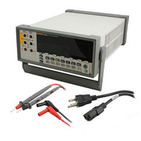
DMM 5.5 RES RS-232 INTERFACE
Manufacturer
Fluke Electronics
Type
Digital (DMM)r
Specifications of 8808A 120V
Includes
Test Leads
Style
Bench
Display Digits
5.5
Display Type
VFD, Dual
Display Count
200000
Function
Voltage, Current, Resistance, Frequency
Functions, Extra
Continuity, dB, Diode Test
Features
Hold, Min/Max, RS-232 Port
Ranging
Auto/Manual
Response
True RMS
Lead Free Status / RoHS Status
Not applicable / RoHS non-compliant
Other names
614-1068


8808A
Users Manual
4-24
Compare Commands and Queries
Trigger Configuration Commands
COMP
COMP?
COMPCLR
COMPHI <high value>
COMPLO <low value>
HOLDCLR
TRIGGER <type>
TRIGGER?
Command
Command
Table 4-13 describes the compare commands and queries. These commands cause the
Meter to determine whether a measurement is higher than, lower than, or within a
specified range. These commands correspond with C, U and V on the front
panel.
Table 4-14 describes the trigger configuration commands, which set and return the trigger
configuration.
Meter enters compare (COMP) function. Touch Hold is automatically turned
on. (Touch Hold can be turned off with HOLDCLR command.)
Meter returns Hl if the last COMP measurement reading was above the upper
limit of the compare range; LO if it was below the lower limit of the compare
range; PASS if within compare range; or a dash (—) if a measurement has
not completed.
Meter exits compare function (and Touch Hold if it is selected) and restores
display to normal operation.
Sets HI compare (COMP) value to <high value>.
<high value> can be a signed integer, signed real number without exponent,
or signed real number with exponent.
Sets LO compare (COMP) value to <low value>.
<low value> can be a signed integer, signed real number without exponent, or
signed real number with exponent.
Meter exits Touch Hold and restores display to normal operation, but does not
exit the compare function.
Sets the trigger configuration to <type> where <type> is the number in the
Type column of Table 4-3 that corresponds with the applicable trigger, rear
trigger and setting delay. If the <type> entered is not between 1 and 5, an
Execution Error is generated.
Select a trigger type with settling delay enabled (trigger type 3 or 5) when the
input signal is not stable before a measurement is triggered. Typical settling
delays are provided in Table 4-3.
Returns the trigger type set by the TRIGGER command.
Table 4-13. Compare Commands and Queries
Table 4-14. Trigger Configuration Commands
Description
Description