8808A/SU 120V Fluke Electronics, 8808A/SU 120V Datasheet - Page 77
8808A/SU 120V
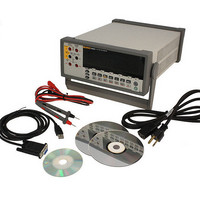
Manufacturer Part Number
8808A/SU 120V
Description
USB CABLE KIT SW DMM 5.5 RES
Manufacturer
Fluke Electronics
Type
Digital (DMM)r
Datasheet
1.8808A_120V.pdf
(100 pages)
Specifications of 8808A/SU 120V
Includes
Test Leads
Style
Bench
Display Digits
5.5
Display Type
VFD, Dual
Display Count
200000
Function
Voltage, Current, Resistance, Frequency
Functions, Extra
Continuity, dB, Diode Test
Features
Hold, Min/Max, RS-232 Port
Ranging
Auto/Manual
Response
True RMS
Lead Free Status / RoHS Status
Not applicable / RoHS non-compliant
Other names
614-1069


Function Commands and Queries
*SRE
*SRE?
*STB?
*TRG
*TST
*WAI
AAC
AACDC
ADC
(Not applicable)
CONT
DIODE
FREQ
Command
Primary Display
Table 4-9 describes function commands and queries. Refer to Chapter 3 for detailed
descriptions of each function.
[1]
Service Request Enable
Service Request Enable
Query
Read Status Byte
Trigger
Self test query
Wait-to-Continue
Commands
AAC2
(Not applicable)
ADC2
CLR2
(Not applicable)
(Not applicable)
FREQ2
Table 4-9. Function Commands and Queries
Secondary Display
Table 4-8. Common Commands (cont.)
Name
Sets the Service Request Enable Register to
<value>, where <value> is an integer between 0 and
255. The value of bit 6 is ignored because the Service
Request Enable Register does not use it.
<value> is an integer whose binary equivalent
corresponds to the state (1 or 0) of bits in the register.
If <value> is not between 0 and 255, an Execution
Error is generated.
Meter returns the <value> of the Service Request
Enable Register (with bit 6 set to 0).
<value> is an integer whose binary equivalent
corresponds to the state (1 or 0) of bits in the register.
Meter returns the <value> of the Status Byte with bit 6
as the Master Summary bit.
<value> is an integer whose binary equivalent
corresponds to the state (1 or 0) of bits in the register.
Causes the Meter to trigger a measurement when
parsed.
Always returns zero.
Do nothing.
Operating the Meter Using the Computer Interface
AC current
AC plus DC rms current
DC current
Clears measurement (if shown)
Continuity test
Diode test
Frequency
Description
Computer Interface Command Set
Function
4-17
4