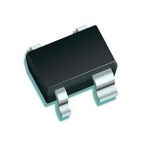
BFP 450 H6327 Infineon Technologies, BFP 450 H6327 Datasheet - Page 11

BFP 450 H6327
Manufacturer Part Number
BFP 450 H6327
Description
RF Bipolar Small Signal RF BIP TRANSISTOR
Manufacturer
Infineon Technologies
Datasheet
1.BFP_450_H6327.pdf
(27 pages)
Specifications of BFP 450 H6327
Dc Collector/base Gain Hfe Min
60
Minimum Operating Temperature
- 65 C
Mounting Style
SMD/SMT
Configuration
Single
Transistor Polarity
NPN
Maximum Operating Frequency
24 GHz
Collector- Emitter Voltage Vceo Max
15 V
Emitter- Base Voltage Vebo
1.5 V
Continuous Collector Current
10 mA
Power Dissipation
450 mW
Maximum Operating Temperature
+ 150 C
Package / Case
SOT-343
Mounting Type
Surface Mount
Power - Max
450mW
Current - Collector (ic) (max)
100mA
Voltage - Collector Emitter Breakdown (max)
4.5V
Gain
15.5dB
Transistor Type
NPN
Frequency - Transition
24GHz
Dc Current Gain (hfe) (min) @ Ic, Vce
60 @ 50mA, 4V
Noise Figure (db Typ @ F)
1.25dB @ 1.8GHz
Lead Free Status / RoHS Status
Lead free / RoHS Compliant
Other names
BFP450H6327XT
4.3
Measurement setup is a test fixture with Bias T’s in a 50 Ω system,
Figure 2
Table 5
Parameter
Maximum power gain
High linearity operation point
Class A operation point
Transducer gain
High linearity operation point
Class A operation point
Minimum noise figure
Minimum noise figure
Associated gain
Linearity
1 dB gain compression point
3rd order intercept point
Data Sheet
IN
Frequency Dependent AC Characteristics
BFP450 Testing Circuit
AC Characteristics,
Bias-T
VB
V
CE
= 3 V,
Symbol
G
G
S
S
NF
G
OP
OIP
21
21
ms
ms
ass
(Pin 1)
min
1dB
E
B
3
f
= 150 MHz
Top View
Min.
–
–
–
–
–
–
–
–
11
Typ.
34.5
35.5
33
33.5
1.55
32
19
30.5
Values
C
E
T
A
= 25 °C
Max.
–
–
–
–
–
–
–
–
Unit
dB
dB
dB
dBm
VC
Bias -T
Electrical Characteristics
Revision 1.0, 2010-10-22
Note / Test Condition
I
I
Z
I
I
Z
I
I
Z
I
I
C
C
C
C
C
C
C
C
S
S
S
= 50 mA
= 90 mA
= 50 mA
= 90 mA
= 50 mA
= 50 mA
= 90 mA
= 90 mA
=
=
=
Z
Z
Z
L
opt
L
= 50 Ω
= 50 Ω
BFP450
OUT


