H7BX-A AC100-240 Omron, H7BX-A AC100-240 Datasheet - Page 21
H7BX-A AC100-240
Manufacturer Part Number
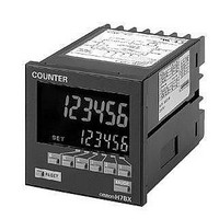
H7BX-A AC100-240
Description
1-stg 72x72 Multifunc Counter
Manufacturer
Omron
Datasheet
1.Y92A-72.pdf
(28 pages)
Specifications of H7BX-A AC100-240
Display Type
LCD Backlight
Lead Free Status / Rohs Status
Lead free / RoHS Compliant


■ Explanation of Functions
Settings marked with a star can be performed with the DIP switch.
Set the output method for control output based on the OUT1/
OUT2 set value. Upper and lower limit (HI-LO), area (AREA),
upper limit (HI-HI), and lower limit (LO-LO) can be set.
(For details on the operation of the output modes, refer to Output
Mode Settings on page 22.)
Set the maximum counting speed (30 Hz/10 kHz) for CP1 input.
If contacts are used for input signals, set the counting speed to
30 Hz. Processing to eliminate chattering is performed for this
setting.
Decide the decimal point position for the measurement value,
OUT1 set value, and OUT2 set value.
It is possible to display the rate of rotation or the speed of a
device or machine to which the H7BX is mounted by converting
input pulses to a desired unit. If this prescaling function is not
used, the input frequency (Hz) will be displayed.
The relationship between display and input is determined by the
following equation. Set the prescale value according to the unit
to be displayed.
1. Displaying the Rotation Rate
N: Number of pulses per revolution
Example: In order to display the rate of rotation for a machine
2. Displaying the Speed
N: Number of pulses per revolution
d: Diameter of rotating body (m)
Flickering display and output chattering can be prevented by
using average processing (simple averaging). Average
processing can be set to one of four levels: no average
processing, 2 times (i.e., the average of 2 measurement values),
4 times, or 8 times.
The measurement cycle will be equal to the sampling cycle
(200 ms) multiplied by the average processing setting (i.e., the
number of times). Average processing enables fluctuating input
signals to be displayed stably. Set the optimum number of times
for the application.
Note: Incorrectly setting the prescale value will result in
d: Circumference (m)
Tachometer Output Mode (totm) ★
Counting Speed (cnts) ★
Decimal Point Position (dp)
Prescale Value (pscl)
Average Processing (aug) ★
Displayed value = f
f: Input pulse frequency (number of pulses in 1 second)
that outputs 5 pulses per revolution in the form @@.@ rpm:
1. Set the decimal point position to 1 decimal place.
2. Using the formula, set the prescale value to 1/N
: Prescale value
60/5 = 12.
counting errors. Check that the setting has been
performed correctly before using the H7BX.
Display unit
Display unit
m/min
rpm
m/s
rps
Prescale value ( )
Prescale value ( )
d
1/N
d
1/N
1/N
1/N
60
60
d: Diameter
of rotating
body
60 =
It is possible to set the H7BX so that if there is no pulse for a
certain time the display is force-set to 0. This time is called the
auto-zero time. Set the auto-zero time to a time slightly longer
than the estimated interval between input pulses. It will not be
possible to make accurate measurements if the auto-zero time is
set to a time shorter than the input pulse cycle. Setting a time
that is too long may also result in problems, such as a time-lag
between rotation stopping and the alarm turning ON.
In order to prevent undesired output resulting from unstable input
immediately after the power supply is turned ON, it is possible to
prohibit measurement for a set time. This time is called the
startup time.
It can also be used to stop measurement and disable output until
the rotating body reaches the normal rate of rotation, after the
power supply to the H7BX and rotating body are turned ON at
the same time.
Select either NPN input (no-voltage input) or PNP input (voltage
input) as the input format. Select an NPN input when using a 2-
wire sensor.
The same setting is used for all external inputs.
For details on input connections, refer to Input Connections on
page 6.
Set the color used for the measurement value.
Note 1. If the tachometer output mode is set to AREA, however, the measured
Set the key protect level.
For details, refer to Key Protect Level on page 24.
(See note 1.)
(See note 2.)
Auto-zero Time (avt) ★
Startup Time (stmr)
NPN/PNP Input Mode (imod) ★
Display Color (colr)
Key Protect Level (kypt)
red
grn
r-g
g-r
2. If the tachometer output mode is set to AREA, however, the measured
value is displayed in red when control output 1 is OFF and in green
when control output 1 is ON.
value is displayed in green when control output 1 is OFF and in red
when control output 1 is ON.
Multifunction Counter
Output (lower limit)
Measured value displayed
in red when both control
outputs 1 and 2 are OFF.
Measured value displayed
in green when both control
outputs 1 and 2 are OFF.
Control output OFF
Power supply
Comparison
(lower limit)
Display
value
Startup time
Green (fixed)
Red (fixed)
Measured value displayed in
green when either control output
1 or control output 2 is ON.
Measured value displayed in red
when either control output 1 or
control output 2 is ON.
H7BX
Control output ON
Time
21
Related parts for H7BX-A AC100-240
Image
Part Number
Description
Manufacturer
Datasheet
Request
R

Part Number:
Description:
G6S-2GLow Signal Relay
Manufacturer:
Omron Corporation
Datasheet:
Part Number:
Description:
Compact, Low-cost, SSR Switching 5 to 20 A
Manufacturer:
Omron Corporation
Datasheet:
Part Number:
Description:
Manufacturer:
Omron Corporation
Datasheet:
Part Number:
Description:
Manufacturer:
Omron Corporation
Datasheet:
Part Number:
Description:
Manufacturer:
Omron Corporation
Datasheet:
Part Number:
Description:
Manufacturer:
Omron Corporation
Datasheet:
Part Number:
Description:
Manufacturer:
Omron Corporation
Datasheet:
Part Number:
Description:
Manufacturer:
Omron Corporation
Datasheet: