F3SP-B1P Omron, F3SP-B1P Datasheet - Page 11
F3SP-B1P
Manufacturer Part Number
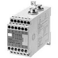
F3SP-B1P
Description
F3SN-A SAFETY RELAY UNIT
Manufacturer
Omron
Datasheet
1.F3SP-B1P.pdf
(27 pages)
Specifications of F3SP-B1P
Supply Voltage Max
24VDC
Light Curtain Type
Safety
Control Output Type
3NO/1NC
Lead Free Status / RoHS Status
Lead free / RoHS Compliant


An Example of Safety Circuits Where No Controller is Used
For category 4 rating
Cable with Connector on
One End (for Emitter)
F39-JC@A-L or
F39-JC@E@-L
An Example of Safety Circuits Where the F3SP-B1P Controller is Used
For category 4 rating
Wiring for the auto-reset mode
E1
+24 VDC
H1
Interlock
selection
0 V
L1
S1
E1
Test
J1
+24 VDC
S2
Emitter
http://www.ia.omron.com/
0 V
S1
Emitter
H1
A1
A2
S3
Reset
PE
X1
H1
K1
OSSD1
F3SP-B1P
RS-485(A) (Gray)
RS-485(B) (Pink)
Cable with Connectors
on Both Ends
F39-JC@B
Interlock
selection
F3SN-A@SS
F3SN-A@SS
L1
Note: 1. If the EDM is not necessary, short-circuit T31 and T32.
OSSD2
K2
Test
J1
2. For the number and arrangement of all terminals on the
S1
KM1
KM2
H1
K1
K2
F3SP-B1P, see the instruction manual packaged together
with the F3SP-B1P.
T31
S2
Receiver
EDM
(External device
monitoring)
Receiver
Reset
KM1
KM2
X1
T32
PLC
IN
Auxiliary
output
Cable with Connector on
One End (for Receiver)
F39-JC@A-D or
F39-JC@E@-D
P1
KM1 KM2
PLC
IN1
KM1
13
14
IN2
23
24
OUT
KM2
33
34
OUT
41
42
M
M
(c)Copyright OMRON Corporation 2007 All Rights Reserved.
KM1
KM2
KM1
KM2
S1: External test switch
S2: Interlock/lockout reset switch
KM1, KM2: Relay with forcibly guided contacts (G7SA)
KM3: Solid-state contactor (G3J)
M: 3-phase motor
E1: 24 VDC power supply (S82K)
PLC: Programmable Controller
KM3
Applicable operation mode
• Manual reset mode
• Using the external relay monitor function
KM3
Applicable operation mode
• Manual reset mode
S1: External test switch
S2: Interlock/lockout reset switch
S3: Lockout reset switch (If the switch is not necessary, connect
KM1, KM2: Relay with forcibly guided contacts (G7SA)
KM3: Solid-state contactor (G3J)
M: 3-phase motor
E1: 24 VDC power supply (S82K)
PLC: Programmable Controller
(Used for monitoring. This is not a part of a safety system.)
between X1 and H1.)
(Used for monitoring. This is not a part of a safety system.)
Timing Chart
Timing Chart
External test switch
External test switch
Light interrupted
Light interrupted
Control output
Control output
Light incident
Light incident
N.O. contact
N.O. contact
N.C. contact
N.C. contact
N.O. contact
N.C. contact
Reset switch
Reset switch
PLC input 1
PLC input 2
(See note.)
KM1, KM2
KM1, KM2
PLC output
PLC output
KM1, KM2
KM1, KM2
PLC input
K1, K2
K1, K2
(S1)
(S2)
(S1)
(S2)
Depends on the operation mode of the auxiliary output
Note: The output operation mode of the auxiliary
output is the Dark-ON output mode.
F3SN-A@SS
11
Related parts for F3SP-B1P
Image
Part Number
Description
Manufacturer
Datasheet
Request
R


Part Number:
Description:
F3S-B OPTIONAL PROGRAMMING KIT
Manufacturer:
Omron
Datasheet:

Part Number:
Description:
G6S-2GLow Signal Relay
Manufacturer:
Omron Corporation
Datasheet:
Part Number:
Description:
Compact, Low-cost, SSR Switching 5 to 20 A
Manufacturer:
Omron Corporation
Datasheet:
Part Number:
Description:
Manufacturer:
Omron Corporation
Datasheet:
Part Number:
Description:
Manufacturer:
Omron Corporation
Datasheet:
Part Number:
Description:
Manufacturer:
Omron Corporation
Datasheet: