F3SP-B1P Omron, F3SP-B1P Datasheet - Page 12
F3SP-B1P
Manufacturer Part Number
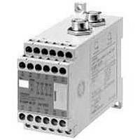
F3SP-B1P
Description
F3SN-A SAFETY RELAY UNIT
Manufacturer
Omron
Datasheet
1.F3SP-B1P.pdf
(27 pages)
Specifications of F3SP-B1P
Supply Voltage Max
24VDC
Light Curtain Type
Safety
Control Output Type
3NO/1NC
Lead Free Status / RoHS Status
Lead free / RoHS Compliant


An Example of Safety Circuits Where the F3SX Safety Controller is Used
(with Two F3SN-A@SS Sets Connected)
F3SX-EL2 (Manual Reset)
For category 4 rating
24 VDC
Timing Chart
Reset switch (S2)
F3SN-A@SS
control outputs
1 and 2
F3SX-EL2
SS1, SS2
KM1, KM2
Motor (M)
Emergency stop
switch (S1)
E1
S1
Wiring for use of the test
function of the Light Curtain
M
Test
switch
A1
A2
24 V
SSC AS3 AS2 AS1
ON
OFF
ON
OFF
ON
OFF
ON
OFF
ON
OFF
Rotate
Stop
Note: This timing chart does not allow for I/O device response delays.
T11 T12 T21 T22
E1
24 V
Control circuits
24 VDC
E1
KM1
KM2
http://www.ia.omron.com/
Reset input
24 VDC
SS1 SS2
KM1 KM2
Y1
0 V
Y2
S2
F39-JC@A-L or
F39-JC@E@-L
Cable with
Connector on One
End (for Emitter)
24 V
FB
Y3
interrupted
E1
F3SN
light
15
2
incident
8
9
F3SN
light
Emitter
Emitter
11
6
Reset input
F3SX-EL2
16
1
F3SN-A@SS
F3SN-A@SS
14
3
RS-485(A)
RS-485(B)
RS-485(B)
RS-485(A)
(gray)
(pink)
(pink)
13
(gray)
4
Emergency
stop switch
12
5
OFF
10
7
Receiver
Receiver
Emergency
stop switch
F39-JC@A-D or
F39-JC@E@-D
Cable with
Connector on One
End (for Receiver)
ON
Reset input
S1:
S2:
KM1, KM2: Relay with forcibly guided contacts
M:
E1:
Note 1: The above circuit diagram conforms to Category 4.
2: In this connection example, the auxiliary output is set to the
standard setting (Dark-ON operation).
To operate using non-standard settings, refer to the catalog or
Instruction Manual for the F3SN-A@SS.
Use the optional F39-MC11 Setting Console to disable the EDM.
(c)Copyright OMRON Corporation 2007 All Rights Reserved.
Emergency stop switch (A165E, A22E)
Reset switch
Three-phase motor
24-VDC power supply (S82K)
F3SN-A@SS
12
Related parts for F3SP-B1P
Image
Part Number
Description
Manufacturer
Datasheet
Request
R


Part Number:
Description:
F3S-B OPTIONAL PROGRAMMING KIT
Manufacturer:
Omron
Datasheet:

Part Number:
Description:
G6S-2GLow Signal Relay
Manufacturer:
Omron Corporation
Datasheet:
Part Number:
Description:
Compact, Low-cost, SSR Switching 5 to 20 A
Manufacturer:
Omron Corporation
Datasheet:
Part Number:
Description:
Manufacturer:
Omron Corporation
Datasheet:
Part Number:
Description:
Manufacturer:
Omron Corporation
Datasheet:
Part Number:
Description:
Manufacturer:
Omron Corporation
Datasheet: