F3SP-B1P Omron, F3SP-B1P Datasheet - Page 16
F3SP-B1P
Manufacturer Part Number
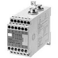
F3SP-B1P
Description
F3SN-A SAFETY RELAY UNIT
Manufacturer
Omron
Datasheet
1.F3SP-B1P.pdf
(27 pages)
Specifications of F3SP-B1P
Supply Voltage Max
24VDC
Light Curtain Type
Safety
Control Output Type
3NO/1NC
Lead Free Status / RoHS Status
Lead free / RoHS Compliant


I/O Circuit
■ Circuit
Note: 1. Open: normal light emission, short: stops light emission
■ Cable with Connector on One End
F39-JC3A (3 m)
F39-JC7A (7 m)
F39-JC10A (10 m)
F39-JC15A (15 m)
F39-JC3E@ (3 m)
F39-JC7E@ (7 m)
F39-JC10E@ (10 m)
F39-JC15E@ (15 m)
External
indicator output
External
indicator output
2. Refer to “Wiring Diagram: Basic Connection” on page 10.
3. The section encircled with the dashed line applies to models ending in -01 and -04 only.
4. The numbers in ❍ indicate pin numbers of the Connector.
(See note 3.)
(See note 3.)
Model
Load
Load
The numbers in ● indicate pin numbers of the series connection Connectors.
0 V
0 V
4
7
8
7
http://www.ia.omron.com/
RS-485(A)
3
4
2
Gray
Gray
5
8
Receiver main
Receiver main
5
5
6
1
Emitter main
circuit 1
circuit 2
7
Display
Display
circuit
6
6
RS-485(B)
Pink
Pink
1
2
3
4
5
6
7
8
Internal wiring
2
3
1
4
7
2
8
3
1
4
7
Control output 1
Control output 2
Brown
Green
White
Yellow
Blue
Brown
Red
Green
White
Yellow
Blue
Auxiliary
Test input (See note 1.)
Interlock selection input
(See note 2.)
Reset input (See note 2.)
output
External relay monitor input
(See note 2.)
Cable sheath color
Load
White
Brown
Green
Yellow
Gray
Pink
Blue
Red
Load
(c)Copyright OMRON Corporation 2007 All Rights Reserved.
Load
1
2
3
4
5
6
7
8
Pin No.
+24 VDC
0 V
White
Brown
Green
Yellow
Gray
Pink
Blue
Red
sheath
Cable
color
Control output 2 Interlock
+24 V
Control output 1 Test input
Auxiliary output
RS-485 (A)
RS-485 (B)
0 V
EDM input
Receiver
F3SN-A@SS
Signal name
selection input
+24 V
Reset input
RS-485 (A)
RS-485 (B)
0 V
N.C.
Emitter
16
Related parts for F3SP-B1P
Image
Part Number
Description
Manufacturer
Datasheet
Request
R


Part Number:
Description:
F3S-B OPTIONAL PROGRAMMING KIT
Manufacturer:
Omron
Datasheet:

Part Number:
Description:
G6S-2GLow Signal Relay
Manufacturer:
Omron Corporation
Datasheet:
Part Number:
Description:
Compact, Low-cost, SSR Switching 5 to 20 A
Manufacturer:
Omron Corporation
Datasheet:
Part Number:
Description:
Manufacturer:
Omron Corporation
Datasheet:
Part Number:
Description:
Manufacturer:
Omron Corporation
Datasheet:
Part Number:
Description:
Manufacturer:
Omron Corporation
Datasheet: