SI7913DN-T1-E3 Vishay, SI7913DN-T1-E3 Datasheet - Page 10
SI7913DN-T1-E3
Manufacturer Part Number
SI7913DN-T1-E3
Description
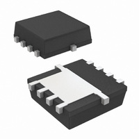
MOSFET DUAL P-CH 20V 1212-8
Manufacturer
Vishay
Series
TrenchFET®r
Specifications of SI7913DN-T1-E3
Fet Type
2 P-Channel (Dual)
Fet Feature
Logic Level Gate
Rds On (max) @ Id, Vgs
37 mOhm @ 7.4A, 4.5V
Drain To Source Voltage (vdss)
20V
Current - Continuous Drain (id) @ 25° C
5A
Vgs(th) (max) @ Id
1V @ 250µA
Gate Charge (qg) @ Vgs
24nC @ 4.5V
Power - Max
1.3W
Mounting Type
Surface Mount
Package / Case
PowerPAK® 1212-8 Dual
Transistor Polarity
P Channel
Continuous Drain Current Id
-7.4A
Drain Source Voltage Vds
-20V
On Resistance Rds(on)
66mohm
Rds(on) Test Voltage Vgs
8V
Threshold Voltage Vgs Typ
-1V
Lead Free Status / RoHS Status
Lead free / RoHS Compliant
Other names
SI7913DN-T1-E3TR


AN822
Vishay Siliconix
CONCLUSIONS
As a derivative of the PowerPAK SO-8, the PowerPAK
1212-8 uses the same packaging technology and has
been shown to have the same level of thermal perfor-
mance while having a footprint that is more than 40 %
smaller than the standard TSSOP-8.
Recommended PowerPAK 1212-8 land patterns are
provided to aid in PC board layout for designs using this
new package.
www.vishay.com
4
105
95
85
75
65
55
45
0.00
Figure 5. Spreading Copper - Si7401DN
0 %
0.25
Spreading Copper (sq. in.)
0.50
0.75
1.00
100 %
1.25
1.50
1.75
50 %
2.00
The PowerPAK 1212-8 combines small size with attrac-
tive thermal characteristics. By minimizing the thermal
rise above the board temperature, PowerPAK simplifies
thermal design considerations, allows the device to run
cooler, keeps r
handle more current than a same- or larger-size MOS-
FET die in the standard TSSOP-8 or SO-8 packages.
Figure 6. Spreading Copper - Junction-to-Ambient Performance
130
120
110
100
90
80
70
60
50
0.00
Spreading Copper (sq. in.)
0.25
DS(ON)
0.50
50 %
low, and permits the device to
0.75
1.00
100 %
1.25
Document Number 71681
1.50
1.75
03-Mar-06
0 %
2.00
Related parts for SI7913DN-T1-E3
Image
Part Number
Description
Manufacturer
Datasheet
Request
R

Part Number:
Description:
Dual P-channel 20-V (d-s) Mosfet
Manufacturer:
Vishay Intertechnology
Datasheet:

Part Number:
Description:
MOSFET P-CH DL 20V PWRPAK 1212-8
Manufacturer:
Vishay
Datasheet:

Part Number:
Description:
357-036-542-201 CARDEDGE 36POS DL .156 BLK LOPRO
Manufacturer:
Vishay
Datasheet:
Part Number:
Description:
357-036-542-201 CARDEDGE 36POS DL .156 BLK LOPRO
Manufacturer:
Vishay
Datasheet:
Part Number:
Description:
357-036-542-201 CARDEDGE 36POS DL .156 BLK LOPRO
Manufacturer:
Vishay
Datasheet:
Part Number:
Description:
357-036-542-201 CARDEDGE 36POS DL .156 BLK LOPRO
Manufacturer:
Vishay
Datasheet:
Part Number:
Description:
357-036-542-201 CARDEDGE 36POS DL .156 BLK LOPRO
Manufacturer:
Vishay
Datasheet:
Part Number:
Description:
357-036-542-201 CARDEDGE 36POS DL .156 BLK LOPRO
Manufacturer:
Vishay
Datasheet:
Part Number:
Description:
357-036-542-201 CARDEDGE 36POS DL .156 BLK LOPRO
Manufacturer:
Vishay
Datasheet:
Part Number:
Description:
357-036-542-201 CARDEDGE 36POS DL .156 BLK LOPRO
Manufacturer:
Vishay
Datasheet:
Part Number:
Description:
357-036-542-201 CARDEDGE 36POS DL .156 BLK LOPRO
Manufacturer:
Vishay
Datasheet:
Part Number:
Description:
357-036-542-201 CARDEDGE 36POS DL .156 BLK LOPRO
Manufacturer:
Vishay
Datasheet:
Part Number:
Description:
357-036-542-201 CARDEDGE 36POS DL .156 BLK LOPRO
Manufacturer:
Vishay
Datasheet:
Part Number:
Description:
357-036-542-201 CARDEDGE 36POS DL .156 BLK LOPRO
Manufacturer:
Vishay
Datasheet:
Part Number:
Description:
357-036-542-201 CARDEDGE 36POS DL .156 BLK LOPRO
Manufacturer:
Vishay
Datasheet: