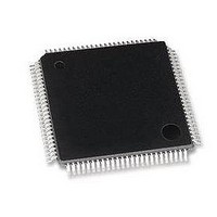
LAN91C96I-MS SMSC, LAN91C96I-MS Datasheet - Page 20

LAN91C96I-MS
Manufacturer Part Number
LAN91C96I-MS
Description
Ethernet ICs Non-PCI 10 Mbps Ethernet MAC
Manufacturer
SMSC
Type
Single Chip MAC and PHYr
Datasheet
1.LAN91C96-MU.pdf
(125 pages)
Specifications of LAN91C96I-MS
Ethernet Connection Type
10 Base-T, 100 Base-TX
Minimum Operating Temperature
0 C
Mounting Style
SMD/SMT
Product
Ethernet Controllers
Number Of Transceivers
1
Standard Supported
802.3, 802.3u
Data Rate
10 Mbps, 100 Mbps
Supply Voltage (max)
5 V
Supply Voltage (min)
0 V
Supply Current (max)
95 mA
Maximum Operating Temperature
+ 70 C
Package / Case
TQFP-100
Lead Free Status / RoHS Status
Lead free / RoHS Compliant
Available stocks
Company
Part Number
Manufacturer
Quantity
Price
Company:
Part Number:
LAN91C96I-MS
Manufacturer:
Standard
Quantity:
399
Revision 1.0 (10-24-08)
11,19,
48,59,
71,79,
TQFP
98,38
91
94
95
83
82
77
76
81
80
85
84
75
73
72
74
66
88
90
89
PIN NO.
13,21,40,
61,100
73,81,
QFP
50,
93
96
97
85
84
79
78
83
82
87
86
77
75
74
76
68
90
92
91
nEN16
XTAL1
XTAL2
RECP/
RECN
TXP/nCOLL
TXN/nCRS
COLP
COLN
TPERXP
TPERXN
TPETXP
TPETXN
TPETXDP
TPETXDN
PWRDWN/
TXCLK
RBIAS
nXENDEC
VDD
AVDD
PIN NAME
DATASHEET
Diff. Input
Analog
Output
Output
Output
TYPE
pullup
pullup
pullup
I with
I with
I with
Input
Input
Input
Diff.
Diff.
Diff.
Diff.
Diff.
Iclk
Iclk
**
**
**
**
**
**
**
**
I
Page 20
Input. When low the LAN91C96 is configured for 16 bit
bus operation. If left open the LAN91C96 works in 8 bit
bus mode. 16 bit configuration can also be
programmed via serial EEPROM or software
initialization of the CONFIGURATION REGISTER.
An external parallel resonance 20MHz crystal should
be connected across these pins. If an external clock
source is used, it should be connected to this pin
(XTAL1) and XTAL2 should be left open.
An external parallel resonance 20MHz crystal should
be connected across these pins. If an external clock
source is used, it should be connected to XTAL1 and
this pin (XTAL2) should be left open.
AUI receive differential inputs.
INTERNAL ENDEC - (nXENDEC pin open). In this
mode TXP and TXN are the AUI transmit differential
outputs. They must be externally pulled up using 150
ohm resistors.
EXTERNAL ENDEC - (nXENDEC pin tied low). In this
mode the pins are inputs used for collision and carrier
sense functions.
AUI collision differential inputs. A collision is indicated
by a 10MHz signal at this input pair.
10BASE-T receive differential inputs.
INTERNAL ENDEC - 10BASE-T transmit differential
outputs.
10BASE-T delayed transmit differential outputs. Used
in combination with TPETXP and TPETXN to generate
the 10BASE-T transmit pre-distortion.
INTERNAL ENDEC - Powerdown input. It keeps the
LAN91C96 in powerdown mode when high (open).
Must be low for normal operation.
EXTERNAL ENDEC - Transmit clock input from
external ENDEC.
A resistor should be connected between this pin and
analog ground to determine the receive threshold
voltage of TX Receive, AUI Receive, AUI Collision
Receive, and AUI transmit voltage.
When tied low the LAN91C96 is configured for
EXTERNAL ENDEC. When tied high or left open the
LAN91C96 will use its internal encoder/decoder.
+5V power supply pins or 3.3V power supply pins
(Revisions E and later)
+5V analog power supply pins or 3.3V power supply
pins (Revisions E and later)
Non-PCI Single-Chip Full Duplex Ethernet Controller with Magic Packet
DESCRIPTION
SMSC LAN91C96 5v&3v
Datasheet


