72-8150 TENMA, 72-8150 Datasheet
72-8150
Specifications of 72-8150


72-8150 Summary of contents
Page 1
... Model 72-8150: OPERATING MANUAL Table of Contents Title Overview Inspection Safety Information Rules For Safe Operation International Electrical Symbols The Meter Structure Functional Buttons Display Symbols Measurement Operation A. Measuring Resistance B. Capacitance Measurement C. Diode and Continuity Test D. Transistor hFE Measurement General Specifications Accuracy Specifications A ...
Page 2
... Model 72-8150: OPERATING MANUAL 2 ...
Page 3
... To avoid electric shock or personal injury, read the “Safety Information” and “Rules for Safety Operation” carefully before using the Meter. Digital Capacitance Meter Model 72-8150 (hereafter referred to as “the Meter” 1/2 digits with steady operations, fashionable design and highly reliable hand- held measuring instrument ...
Page 4
... Item Description 1 English Operating Manual 2 Test Clip 3 9V Battery (NEDA1604, 6F22 or 006P) (installed) In the event you find any items missing or damaged, please contact your dealer immediately. Model 72-8150: OPERATING MANUAL Qty 1 piece 1 pair 1 piece 4 ...
Page 5
... Model 72-8150: OPERATING MANUAL Safety Information This Meter complies with the standards EMC EN61326. Use the Meter only as specified in this operating manual, otherwise the protection provided by the Meter may be impaired. In this manual, a Warning identifies conditions and actions that pose hazards to the user, and may damage the Meter or the equipment under test ...
Page 6
... Replace the battery as soon as the battery indicator appears. With a low battery, the Meter might produce false readings that can lead to electric shock and personal injury. l Remove test clips from the Meter and turn the Meter power off before opening the Meter case. Model 72-8150: OPERATING MANUAL 6 ...
Page 7
... Model 72-8150: OPERATING MANUAL l When servicing the Meter, use only the same model number or identical electrical specifications replacement parts. l The internal circuit of the Meter shall not be altered at will to avoid damage of the Meter and any accident. l Soft cloth and mild detergent should be used to clean the surface of the Meter when servicing ...
Page 8
... International Electrical Symbols Ground Double Insulated Low Battery. Continuity Test. Diode. Capacitance Test Fuse. Warning. Refer to the Operating Manual. Conforms to Standards of European Union. Model 72-8150: OPERATING MANUAL 8 ...
Page 9
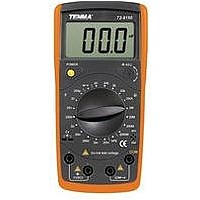
... Model 72-8150: OPERATING MANUAL The Meter Structure (figure 1) 1. LCD Display 2. Capacitance Zero Adjustment Switch 3. Transistor Jack 4. Resistance, Diode and Continuity Buzzer Input Terminal 5. Capacitance Input Terminal 6. Small Value Capacitance Jack 7. Rotary Switch . 8. Power Button Functional Buttons Below table indicated for information about the functional button operations ...
Page 10
... Picofarad. 1x10 F, mF farads. nF: Nanofarad. 1x10 µF: Microfarad.1x10 mF: Millifarad. 1x10 : Ohm. The unit of resistance kilohm. 1x10 Megaohm. 1x10 H: Henry. The unit of Inductance mH: Millihenry. 1x10 Model 72-8150: OPERATING MANUAL 6 mF µ -12 or 0.000000000001 -9 or 0.000000001 farads 0.000001 farads 0.001 farads. ...
Page 11
... Model 72-8150: OPERATING MANUAL Measurement Operation l Make sure the Low Battery Display otherwise false readings may be provided. l Pay extra attention to the measurement, which is located besides the input terminals of the Meter. A. Measuring Resistance (see figure 3) Warning To avoid damage to the Meter or to the devices under test, disconnect circuit power and discharge all the high-voltage capacitors before measuring resistance ...
Page 12
... For high resistance measurement (> normally requires several seconds to obtain a stable reading. l When resistance measurement has been completed, disconnect the connection between the test clips and the circuit under test and remove the test clips from the input terminals of the Meter. Model 72-8150: OPERATING MANUAL 12 ...
Page 13
... Model 72-8150: OPERATING MANUAL B. Capacitance Measurement (see figure 4) Warning To avoid damage to the Meter or to the equipment under test, disconnect circuit power and discharge all high-voltage capacitors before measuring capacitance. The Meter’s capacitance ranges are:200pF, 2nF, 20nF, 200nF, 2µF, 20µF, 200µF, 2mF and 20mF. ...
Page 14
... Small Value Capacitance Jack when measuring small value of capacitance. l When capacitance measurement has been completed, disconnect the connection between the test clips and the circuit under test and remove the test clips from the input terminals of the Meter. Model 72-8150: OPERATING MANUAL 14 ...
Page 15
... Model 72-8150: OPERATING MANUAL C. Diode and Continuity Test (see figure 5) Warning To avoid damage to the Meter or to the devices under test, disconnect circuit power and discharge all the high-voltage capacitors before measuring diodes and continuity. Testing Diodes Use the diode test to check diodes, transistors, and other semiconductor devices ...
Page 16
... The LCD displays “1” indicating the circuit being tested is open. l When continuity test has been completed, disconnect the connection between the test clips and the circuit under test and remove them from the input terminals of the Meter. Model 72-8150: OPERATING MANUAL terminal and . 16 ...
Page 17
... Model 72-8150: OPERATING MANUAL D. Transistor hFE Measurement (see figure 6) (figure 6) To measure transistor, set up the Meter as follows: 1. Check that the transistor is PNP or NPN type. 2. Insert the transistor to be measured to the corresponding Transistor Jack. 3. The Meter displays the tested transistor’s nearest value. ...
Page 18
... Storage: 10000 m. l Battery Type: One piece of 9V NEDA1604 or 6F22 or 006P. l Low Battery: Display l Dimensions: 6.77" (H) x 3.27" (W) x 1.50" (D). l Weight: Approximate 310g (battery included). l Safety/Compliances: EMC EN61326. l Certification & CUL pending. Model 72-8150: OPERATING MANUAL (32 F ~104 F (14 F ~122 F ...
Page 19
... Model 72-8150: OPERATING MANUAL Accuracy Specifications Accuracy: (a% reading + b digits), guarantee for 1 year. Operating temperature: 23 Relative humidity: <75%. Temperature coefficient: 0.1 x (specified accuracy Resistance Test Range Resolution 20 0.01 200 0.1 2k 0.001k 20k 0.01k 200k 0.1k 2M 0.001M 20M 0.01M 200M 0.1M 2000M 1M Remarks: ...
Page 20
... Measure of Capacitance: 1F= Continuity & Diodes Function Range Diode Continuity Remarks: l Diode: Open Circuit Voltage around 2.8V. l Continuity Around < 120 Model 72-8150: OPERATING MANUAL Testing Accuracy Frequency 800Hz (0.5%+10) (2%+ µ Overload Resolution Protection 1mV 250V rms 1 beeper sounds continuously. ...
Page 21
... Model 72-8150: OPERATING MANUAL D. Transistor Range Resolution hFE 1 Remarks: l The display value is the tested transistor’s nearest value (0~1000 ). Testing Overload Condition Protection Vce 2.8V 250V rms I bo 10µA 21 ...
Page 22
... Turn the Meter power off when it is not in use and take out the battery when not using for a long time not store the Meter in a place of humidity, high temperature and strong magnetic field. Model 72-8150: OPERATING MANUAL 22 ...
Page 23
... Model 72-8150: OPERATING MANUAL B. Replacing the Battery (see figure 7) Warning To avoid false readings, which could lead to possible electric shock or personal injury, replace the battery as soon as the battery indicator “ To replace the battery: 1. Turn the Meter power off and remove all connections from the terminals ...
Page 24
... Fuse 1: 0.315A, 250V, fast type fuse, 5x20 mm. 6. Replace the battery compartment and the case top, and reinstall the screw. 7. Replace the case bottom and case top, and reinstall the screws. Model 72-8150: OPERATING MANUAL (figure 8) 24 ...
Page 25
... Model 72-8150: OPERATING MANUAL Fuse replacement is seldom required. Blown fuses are typically a result of improper use. This operating manual is subject to change without notice. ** END ** 25 ...
Page 26
... Copyright 2006 Tenma Test Equipment. All rights reserved. Tenma Test Equipment 405 S. Pioneer Blvd. Springboro,Ohio 45066 www.tenma.com Model 72-8150: OPERATING MANUAL 26 ...