72-8150 TENMA, 72-8150 Datasheet - Page 16
72-8150
Manufacturer Part Number
72-8150
Description
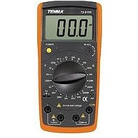
Capacitance Meter With Resistance
Manufacturer
TENMA
Datasheet
1.72-8150.pdf
(26 pages)
Specifications of 72-8150
Accuracy %
2%
External Height
6.77"
External Width
3.27"
External Depth
1.5"
No. Of Batteries
1
Kit Contents
Capacitance Meter, Test Clips, Owners Manual, 1 9V Battery
Lead Free Status / RoHS Status
na


Note
l
l
l
Testing for Continuity
To test for continuity, connect the Meter as below:
1.
2.
3.
4.
5.
Note
l
l
In a circuit, a good diode should still produce a forward
voltage drop reading of 0.5V to 0.8V; however, the
reverse voltage drop reading can vary depending on the
resistance of other pathways between the probe tips.
Connect the test clips to the proper terminals as said
above to avoid error display. The LCD will display “1”
indicating open-circuit for wrong connection. The unit of
diode is Volt (V), displaying the positive-connection
voltage-drop value.
When diode measurement has been completed,
disconnect the connection between the test clips and
the circuit under test and remove them from the input
terminals of the Meter.
The LCD displays “1” indicating the circuit being tested
is open.
When continuity test has been completed, disconnect
the connection between the test clips and the circuit
under test and remove them from the input terminals of
the Meter.
Insert the red test clip into the
the black test clip into the COM terminal.
Set the rotary switch to
Connect the test clips across with the object being
measured.
The beeper sounds continuously when the test resistance
<120 .
The Meter displays the value of the test resistance.
16
Model 72-8150: OPERATING MANUAL
.
terminal and