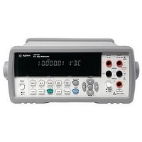
34410A AGILENT TECHNOLOGIES, 34410A Datasheet - Page 8

34410A
Manufacturer Part Number
34410A
Description
MULTIMETER, DIGITAL, BENCH, 6-1/2 DIGIT
Manufacturer
AGILENT TECHNOLOGIES
Datasheet
1.34410A.pdf
(20 pages)
Specifications of 34410A
Dmm Type
Bench
Voltage Measuring Range Dc
100mV To 1000V
Voltage Measuring Range Ac
100mV To 750V
Current Measuring Range Dc
100µA To 3A
Current Measuring Range Ac
100µA To 3A
Lead Free Status / RoHS Status
na
Testing fluorescent ballasts
using direct-sampled ACV
When a fluorescent lamp is off,
the mercury/gas mixture within
the tube is non-conductive. When
power is first applied, 300 VAC
is needed to initiate a gas dis-
charge of mercury radiation.
The electric current passing
through the low-pressure gas
emits UV light. The internal
phosphor coating efficiently
converts most of the U V to
visible light. Once the initial
discharge takes place, a much
lower voltage – usually a
voltage from 100 VAC to
175 VAC – is needed to main-
tain the discharge, dependent
upon the wattage rating of
the bulb.
A DMM is needed to test
the ballast voltages to assure
the correct voltages are being
applied. This is an ACV mea-
surement. Many DMMs, including
the Agilent 34401A, use an
analog RMS converter for
ACV measurements. Although
these converters can measure
frequency content as high as
1 MHz, they do not do a very
good job of telling the DMM
that short-duration, high-
voltage spikes may be present
on the input. These short spikes
may have little impact on
RMS content, so the resulting
voltage measurement may
hardly deviate from the
expected voltage.
For example, the ballast may
actually generate 1-kV or
higher spikes along with the
300-VAC signal needed for
initial startup. The DMM may
read 300 VAC and occasionally
301 VAC. The test system thinks
that is just fine – well within
tolerance. However, you do
not see the huge voltage spikes
pounding against the input
section of the DMM. If the
DMM does not have effective
input protection, the input
circuitry can eventually fail
after continued abuse.
The 34410A and 34411A use
a direct sampling technique to
make AC RMS measurements.
Relative to analog RMS calcu-
lations, the direct sampling
technique offers four primary
advantages: 10-times faster
AC measurements, improved
accuracy for high-frequency
sinusoids, peak-to-peak infor-
mation, and no crest factor
de-rating.
Figure 3. Ballast voltage needed to start a fluorescent bulb and then keep it lit
Initial Discharge – 300 VAC
8
Significant over-sampling of
the input signal can detect the
narrow, high-voltage spikes,
and the DMM can then respond
to those spikes with an overload
error condition. This informs
the test engineer that a problem
exists either in the wiring
connections to the DMM or in
the ballast. The solution can be
as simple as adding filtering in
the fixture to suppress expected
spikes before arriving at the
input terminals of the DMM.
Either way, the test engineer
is better informed by a DMM
that can “see” that actual content
of the signal. Direct-sampled
AC provides that visibility into
signal content, so both RMS
and peak measurements can
be made simultaneously.
Steady State – 100 VAC


