72-1015 TENMA, 72-1015 Datasheet
72-1015
Specifications of 72-1015


72-1015 Summary of contents
Page 1
... Model 72-1015 OPERATING MANUAL ...
Page 2
...
Page 3
... Model 72-1015: OPERATING MANUAL TABLE OF CONTENTS TITLE Overview Inspection Safety Information Rules For Safe Operation International Electrical Symbols The Meter Structure Rotary Switch Functional Buttons Display Symbols Measurement Operation Operation of Hold Mode The POWER Button The SELECT Button Turning on the Display Backlight ...
Page 4
... TITLE POWER INPUT Switch Sleep Mode RS232 Button General Specifications Accuracy Specifications Maintenance RS232C Serial Port System Requirements for Installing the 72-1015 Interface Program RS232C Serial Port Voltage B. AC Voltage C. DC Current D. AC Current E. Resistance F. Continuity Test G. Diode Test H. Capacitance I . Frequency J ...
Page 5
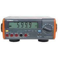
... Information” and “Rules for Safety Operation” carefully before using the Meter Model 72-1015 (hereafter referred to as “the Meter”) has auto and manual range options with maximum reading of 5999 counts and 3-5/6 digits which has a unique outlook design. ...
Page 6
... Point Contact Temperature Probe (to be used under 230 6 Power Cord 7 RS232C Interface Cable 8 Installation guide and computer interface software (CD-ROM) In the event that items are found missing or damaged, contact your Tenma dealer immediately. 4 Model 72-1015: OPERATING MANUAL Description 0 C temperature measurement) Qty 1 piece 1 pair 1 pair 1 piece ...
Page 7
... Model 72-1015: OPERATING MANUAL Safety Information This Meter complies with the standards IEC61010: in pollution degree 2, overvoltage category (CAT. I 1000V, CAT.II 600V) and double insulation. CAT III: Distribution level, fixed installation, with smaller transient overvoltages than CAT. IV CAT IV: Primary supply level, overhead lines, cable systems etc ...
Page 8
... To prevent potential damage to the meter, do not change range or mode during measurement. 6 Model 72-1015: OPERATING MANUAL l When the Meter working at an effective voltage over 60V DC, or 30V RMS AC, special care should be taken for there is danger of electric shock. ...
Page 9
... Model 72-1015: OPERATING MANUAL l Replace the battery as soon as the battery indicator appears. With a low battery, the Meter might produce false readings that can lead to electric shock and personal injury. l Remove test leads, temperature probe, RS232C interface cable, and alligator clip from the Meter and turn the Meter power off before opening the Meter case ...
Page 10
... International Electrical Symbols Ground Double Insulated Warning. Refer to the Operating Manual Low Battery Continuity Test Diode Capacitance Test Fuse Conforms to Standards of European Union 8 Model 72-1015: OPERATING MANUAL ...
Page 11
... Model 72-1015: OPERATING MANUAL The Meter Structure (see figure 1) 1. LCD Display 3. Input Terminals (Figure 1) 2. Rotary Switch 4. Functional Buttons 9 ...
Page 12
... Capacitance test Hz Hz :Frequency measurement :Temperature in Fahrenheit Temperature in celsius hFE Transistor test current measurement range from 0.1uA to 5999uA current measurement range from 0.01mA to 599.9mA current measurement range from 0.01A to 10.00A. 10 Model 72-1015: OPERATING MANUAL Function ...
Page 13
... Model 72-1015: OPERATING MANUAL Functional Buttons Below table indicated for information about the functional button operations. Button POWER Turn the power on and off. LIGHT Turn the display backlight on and off. l SELECT Switches between AC and DC measurement. l Switches between continuity, diode and resistance measurements l Switches between frequency and Fahrenheit temperature ...
Page 14
... Display Symbols (see figure 5.6.7 Auto Range Manual AC+DC Trus RMS 14 RS232 HOLD MAX hFE MIN (Figure 2) Model 72-1015: OPERATING MANUAL 0 C umVA ~mV Trms DC munF ...
Page 15
... Model 72-1015: OPERATING MANUAL Number Meaning Symbol 1 True RMS Indicator for true rms value. 2 HOLD Data hold is active. 3 Sleep Mode feature is enabled. 4 Indicates negative reading Indicator for AC voltage or current Indicator for DC voltage or current 7 AC+DC Indicator for AC+DC measurement 8 OL The input value is too large for the selected range. ...
Page 16
... Centigrade temperature Temperature in Fahrenheit Hz, kHz Hertz. The unit of frequency in cycles/second. MHz kHz : Kilohertz MHz: Megahertz Unit of transistor. 10 Test of diode 11 The continuity buzzer is on. 14 Model 72-1015: OPERATING MANUAL -3 or 0.001 volts 0.001 farads -6 or 0.000001 farads 0.000000001 farads 1,000 hertz 1,000,000 hertz. ...
Page 17
... Model 72-1015: OPERATING MANUAL Number Meaning Symbol 12 AutoRange Indicator of Auto or manual range Manual 13 MAX MIN Display of maximum or minimum value. RS232 14 Data output is in progress. 15 The battery is low. Warning: To avoid false readings, which could lead to possible electric shock or personal injury, replace the battery as soon as the battery indicator appears. ...
Page 18
... Set the rotary switch press SELECT button to select measurement mode. 3. Connect the test leads across with the object being measured. The measured value shows on the display. AC measurement displays True RMS value. 16 Model 72-1015: OPERATING MANUAL (Figure 3) ...
Page 19
... Model 72-1015: OPERATING MANUAL 4. Press AC/AC+DC button to measure AC+DC voltage’s true RMS. Note l In each range, the Meter has an input impedance of 10M except 600mV range has 3000M . This loading effect can cause measurement errors in high impedance circuits. If the circuit impedance is less than or equal to 10k , the error is negligible (0 ...
Page 20
... A , press SELECT button to select measurement mode. 3. Connect the test leads in series with the object being measured. The measured value shows on the display. AC measurement displays True RMS value. 4. Press AC/AC+DC button to measure AC+DC current’s true RMS 18 Model 72-1015: OPERATING MANUAL (Figure 4) ...
Page 21
... Model 72-1015: OPERATING MANUAL Note l If the value of current to be measured is unknown, use the maximum measurement position, and reduce the range step by step until a satisfactory reading is obtained. l For safety sake, each measurement time of high current (>5A) should be less than 10 seconds and the interval time between 2 measurements should be greater than 15 minutes ...
Page 22
... COM terminal Set the rotary switch to , press SELECT button to select measurement mode Connect the test leads across with the object being measured. The measured value shows on the display. 20 Model 72-1015: OPERATING MANUAL (Figure 5) ...
Page 23
... Model 72-1015: OPERATING MANUAL Note l When measuring low resistances, the test leads and internal wiring will add approximately 0.2 of error. To obtain accurate readings in low-resistance, short-circuit the test lead beforehand and record the reading obtained, call this reading as X. Then use the equation: measured resistance value (Y) – ...
Page 24
... The buzzer sounds if the resistance of a circuit under test is < the circuit is in good condition. The buzzer does not sound if the resistance of a circuit under test is >70 , the circuit is broken. 4. The measured value shows on the display and the unit Model 72-1015: OPERATING MANUAL (Figure 6) ...
Page 25
... Model 72-1015: OPERATING MANUAL Note l In continuity mode, the resistance range is 600 , and the open circuit voltage is approximately 1.2V. l When continuity testing has been completed, disconnect the connection between the test leads and the circuit under test, and remove the test leads from the input terminals of the Meter ...
Page 26
... Use the diode test to check diodes, transistors, and other semiconductor devices. The diode test sends a current through the semiconductor junction, and then measures the voltage drop across the junction. A good silicon junction drops between 0.5V and 0.8V. 24 Model 72-1015: OPERATING MANUAL (Figure 7) ...
Page 27
... Model 72-1015: OPERATING MANUAL To test a diode out of a circuit, connect the Meter as follows: 1. Insert the red test lead into terminal and the black test lead into the COM terminal. 2. Set the rotary switch to and press SELECT button to select measurement mode. 3. For forward voltage drop readings on any semiconductor component, place the red test lead on the component’ ...
Page 28
... Insert the red test lead into the Hz mV terminal and the black test lead into the COM terminal. 2. Set the rotary switch Connect the test leads across with the object being measured. The measured value shows on the display. 26 Model 72-1015: OPERATING MANUAL (Figure 8) ...
Page 29
... Model 72-1015: OPERATING MANUAL Note l The Meter displays a fixed value which is the distributed capacitor’s value of the inside Meter. To ensure accuracy necessary to subtract this value from the measured value when measuring small capacitor. l Multi-purpose socket can be used instead of test leads. Insert the capacitor being tested into the corresponding input terminal of the multi-purpose socket ...
Page 30
... Insert the red test lead into the Hz terminal and the black test lead into the COM terminal Set the rotary switch and press SELECT button to select Hz measurement mode. 3. Connect the test leads across with the object being measured. The measured value shows on the display. 28 Model 72-1015: OPERATING MANUAL (Figure 9) ...
Page 31
... Model 72-1015: OPERATING MANUAL Note l When making frequency measurements, the measured signal "a", must fall within the following voltage level: When 10Hz ~ 1MHz :150mV When > 1MHz~ 10MHz :300mV When > 10MHz~ 50MHz :600mV When > 50MHz :Unspecified l When frequency measurement is complete, disconnect the test leads from the circuit under test, and remove from the input terminals of the meter ...
Page 32
... Insert the temperature probe to the corresponding input terminal of the multi-purpose socket. Take care to ensure that proper polarity is observed when connecting to this socket. 4. Place the temperature probe to the object being measured. The measured value shows on the display after few seconds. 30 Model 72-1015: OPERATING MANUAL (Figure 10) ...
Page 33
... Model 72-1015: OPERATING MANUAL Note l The testing environment must between 18 to ensure accuracy especially when measuring low temperature. l Different reading may be obtained when testing room environment under short or open circuit situation, then short-circuited reading shall be considered as the correct reading. l The included point contact temperature probe can ...
Page 34
... The measured nearest transistor value shows on the display. Note l When transistor measeurement has been completed, remove the tested transistor from the multi-purpose socket and remove the multi-purpose scoket from the input terminal 32 Model 72-1015: OPERATING MANUAL PNP NPN (Figure 11) ...
Page 35
... Model 72-1015: OPERATING MANUAL Operation of Hold Mode Warning To avoid possibility of electric shock, do not use Hold mode to determine if circuits are without power. The Hold mode will not capture unstable or noisy readings. The Hold mode is applicable to all measurement functions. l Press HOLD to enter Hold mode. ...
Page 36
... Press LIGHT button again to turn the Display Backlight off. l When using the AC power, the Display Backlight always stays on. 34 Model 72-1015: OPERATING MANUAL The RANGE Button l Press RANGE to enter the manual ranging mode. l Press and hold RANGE for over 1 second to return ...
Page 37
... Model 72-1015: OPERATING MANUAL The MAX MIN Button MAX MIN recording mode captures and stores the maximum and minimum input value detected. To use the MAX MIN mode as follows: l Press MAX MIN to display the highest reading ( MAX is shown on display). l Press MAX MIN again to display the lowest reading ( MIN is shown on display) ...
Page 38
... RANGE, or RS232 button while turning on the Meter, the symbol disappears. 36 Model 72-1015: OPERATING MANUAL RS232 Button Press RS232 button to enter or exit data output mode. In RS232C serial port data output mode, the Hold and Max Min mode cannot output to the computer, the computer will only display the present measuring value ...
Page 39
... Model 72-1015: OPERATING MANUAL General Specifications Maximum Voltage between any Terminals and l Grounding: Refer to different range input protection voltage. l Fused Protection for Hz mV Input Terminal: 200mA, 250V, fast type, 5x20mm (only apply on hFE functions) l Fused Protection for µAmA Input Terminal: 500mA, 125V, fast type, 5x20mm. ...
Page 40
... Relative humidity: not more than 75% RH. Temperature coefficient: 0.1 x (specified accuracy)/ Voltage Range 600mV 6V 60V 600V 1000V Remarks: l Input Impedance: At 600mV range : Around > 3000M . At all other ranges: Around 10M . Resolution Accuracy 0.1mV (0.6%+2) 0.001V 0.01V (0.3%+2) 0.1V 1V (0.5%+3) Model 72-1015: OPERATING MANUAL Overload Protection 1000V ...
Page 41
... Model 72-1015: OPERATING MANUAL B. AC Voltage Range Resolution 600mV 6V 60V 600V 1000V Accuracy 40Hz-50kHz: (0.6%+5) 0.1mV >50kHZ-100kHz: (1%+5) 40Hz-1kHz: (0.6%+5) >1kHz-10kHz: (1.0%+5) 0.001V >10kHz-100kHz: (3%+5) 40Hz-1kHz: (0.6%+5) >1kHz-10kHz: (1.5%+5) 0.01V >10kHz-20kHz: (3%+5) >20kHz-100kHz: (8%+5) 40Hz-1kHz: (0.6%+5) 0.1V >1kHz-10kHz: (3.5%+5) 40Hz-1kHz: (1.2%+3) 1V > ...
Page 42
... True RMS (applicable to the range of 10%~95%) At 1000V range: AC peak factor 1.5. All other ranges: AC peak factor 3.0. Input short circuit has around less than 30 remaining digits, it will not affect accuracy. AC+DC measurement accuracy = range's accuracy + 1% 40 Model 72-1015: OPERATING MANUAL ...
Page 43
... Model 72-1015: OPERATING MANUAL C. DC Current Range 600µA 6000µA 60mA 600mA 10A Remarks range: Continuous measurement is allowed >5A range: For continuous measurement 10 seconds and interval not less than 15 minutes. Resolution Accuracy 0.1µA 1µA (0.5%+3) 0.01mA 0.1mA (0.8%+3) 10mA (1 ...
Page 44
... Input short circuit has around less than 30 remaining digits, it will not affect accuracy. AC+DC measurement accuracy = range's accuracy + 1% 42 Accuracy 40Hz~10kHz: (1.0%+5) 1µA >10kHz~15kHz: (2%+5) 40Hz~10kHz: (1%+5) >10kHz~15kHz: (3%+5) 40Hz~5kHz: (2.0%+6) Model 72-1015: OPERATING MANUAL Overload Protection Fuse 500mA, 125V, fast type, 5x20mm. Fuse 10A,250V, fast type, 5x20mm. ...
Page 45
... Model 72-1015: OPERATING MANUAL E. Resistance Range Resolution 600 0.1 6k 0.001k 60k 0.01k 600k 0.1k 6M 0.001M 60M 0.01M Accuracy Overload Protection (0.8%+3) + test lead short circuit resistance value (0.5%+2) (0.8%+2) (1.2%+3) 250V rms 43 ...
Page 46
... When circuit disconnected with resistance value 250V rms > buzzer does not beep. l When circuit is in good connection with resistance value 70 Overload Protection l Open circuit voltage approximate 2.7V. 250V rms l Working current approximate 1mA. Model 72-1015: OPERATING MANUAL Remarks buzzer beeps continuously. Remarks ...
Page 47
... Model 72-1015: OPERATING MANUAL H. Capacitance Range 6nF 60nF 600nF 6µF 60µF 600µF 6mF Remarks 6nF, 60nF and 600nF Range: reading must subtract Resolution Accuracy 0.001nF (2.5%+5) 0.01nF 0.1nF (2%+5) 0.001µF 0.01µF (3%+4) 0.1µF (5%+4) 0.001mF the test lead open circuit capacitance value. ...
Page 48
... Input scope (a): (DC electric level is zero) When 10Hz ~ 1MHz : 150mV When > 1MHz ~ 10MHz : 300mV When > 10MHz ~ 50MHz : 600mV When > 50MHz : Unspecified 46 Resolution Accuracy 0.001kHz 0.01kHz (0.1%+3) 0.1kHz 0.001MHz 0.01MHz a 30V rms a 30V rms a 30V rms Model 72-1015: OPERATING MANUAL Overload Protection 250V rms ...
Page 49
... Model 72-1015: OPERATING MANUAL J. Temperature Range Resolution Remarks: l The included point contact temperature probe can only be used to measure under 230 measurement higher than that, the rod type temperature probe must be used instead. K. Transistor Range Resolution hFE 1 Accuracy 0 0 -40 C~0 C (8%+ >0 ...
Page 50
... To avoid electrical shock or damage to the Meter, do you get water inside the case. 48 Model 72-1015: OPERATING MANUAL A. General Service l Periodically wipe the case with a damp cloth and mild detergent. Do not use abrasives or solvents. ...
Page 51
... Model 72-1015: OPERATING MANUAL B. Replacing the Fuses (see figure 12) Warning To avoid electrical shock or arc blast, or personal injury or damage to the Meter, use specified fuses ONLY in accordance with the following procedure. To replace the Meter’s fuse: 1. Press the POWER to turn the Meter off, disconnect the power cord and remove all connections from the terminals ...
Page 52
... Fuse 1: 500mA, 125V, fast type, 5x20mm (AC125V) Fuse 2: 10A, 250V, fast type, 5x20 mm (µA, mA) Fuse 3: 500mA, 125V, fast type, 5x20 mm (A) Fuse 4: 200mA, 250V, fast type, 5x20 mm (hFE) Replacement of the fuses is seldom required. Burning of a fuse always results from improper operation. 50 Model 72-1015: OPERATING MANUAL ...
Page 53
... Model 72-1015: OPERATING MANUAL C. Replacing the Battery (see figure 13) Warning To avoid false readings, which could lead to possible electric shock or personal injury, replace the battery as soon as the battery indicator “ ” appears when using battery to power on the Meter. To replace the battery: 1. Press the POWER to turn the Meter off and remove all connections from the terminals ...
Page 54
... RS232C Serial Port System Requirements for Installing the 72-1015 Interface Program To use 72-1015 Interface Program, you need the following hardware and software IBM PC or equivalent computer with 80486 or higher processor and 600 x 800 pixel or better monitor. l Microsoft Windows 95 or above least 8MB of RAM. ...
Page 55
... Model 72-1015: OPERATING MANUAL B. RS232C Port Cable The Meter Computer D-sub D-sub 9 Pin Male 9 Pin Female 25 Pin Female 1 (DCD) 1 (DCD) 2 (RXD) 3 (TXD) 3 (TXD) 2 (RXD) 4 (DTR) 4 (DTR) 5 (SG) 5 (SG) 6 (DSR) 6 (DSR) 7 (RTS) 7 (RTS) 8 (CTS) 8 (CTS) 9 (RI) 9 (RI) C. Setting of RS232C Serial Ports Default of RS232C serial port for communication is set as: ...
Page 56
... Model 72-1015: OPERATING MANUAL Copyright 2005 Tenma Test Equipment. All rights reserved. Tenma Test Equipment 405 S. Pioneer Blvd. Springboro,Ohio 45066 www.tenma.com ...