NDF05N50ZG ON Semiconductor, NDF05N50ZG Datasheet - Page 6
NDF05N50ZG
Manufacturer Part Number
NDF05N50ZG
Description
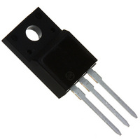
MOSFET N-CH 500V TO-220FP
Manufacturer
ON Semiconductor
Datasheet
1.NDD05N50ZT4G.pdf
(10 pages)
Specifications of NDF05N50ZG
Package / Case
TO-220-3 Full Pack (Straight Leads)
Mounting Type
Through Hole
Power - Max
28W
Fet Type
MOSFET N-Channel, Metal Oxide
Gate Charge (qg) @ Vgs
18.5nC @ 10V
Vgs(th) (max) @ Id
4.5V @ 50µA
Current - Continuous Drain (id) @ 25° C
5A
Drain To Source Voltage (vdss)
500V
Fet Feature
Standard
Rds On (max) @ Id, Vgs
1.5 Ohm @ 2.2A, 10V
Configuration
Single
Transistor Polarity
N-Channel
Resistance Drain-source Rds (on)
1.25 Ohms
Forward Transconductance Gfs (max / Min)
3.5 S
Drain-source Breakdown Voltage
500 V
Continuous Drain Current
5 A
Power Dissipation
28 W
Maximum Operating Temperature
+ 150 C
Mounting Style
Through Hole
Gate Charge Qg
18.5 nC
Minimum Operating Temperature
- 55 C
Lead Free Status / RoHS Status
Lead free / RoHS Compliant
Available stocks
Company
Part Number
Manufacturer
Quantity
Price
Company:

Part Number:
NDF05N50ZG
Manufacturer:
ON
Quantity:
5 950


** For more information about mounting power semiconductors see Application Note AN1040.
torque of 6 to 8 in
pressure on the package over time and during large temperature excursions.
cause the plastic to crack around the mounting hole, resulting in a loss of isolation capability.
package. However, in order to positively ensure the package integrity of the fully isolated device, ON Semiconductor does not
recommend exceeding 10 in
0.01
100
0.1
10
Laboratory tests on a limited number of samples indicate, when using the screw and compression washer mounting technique, a screw
Destructive laboratory tests show that using a hex head 4−40 screw, without washers, and applying a torque in excess of 20 in
Additional tests on slotted 4−40 screws indicate that the screw slot fails between 15 to 20 in
1E−06
1
50% (DUTY CYCLE)
5.0%
2.0%
1.0%
20%
10%
SINGLE PULSE
1E−05
.
lbs is sufficient to provide maximum power dissipation capability. The compression washer helps to maintain a constant
Figure 16. Thermal Impedance (Junction−to−Ambient) for NDD05N50Z
Measurement made between leads and heatsink with all leads shorted together.
.
lbs of mounting torque under any mounting conditions.
1E−04
PLAIN WASHER
NUT
4-40 SCREW
HEATSINK
COMPRESSION WASHER
Figure 18. Typical Mounting Techniques*
Figure 17. Isolation Test Diagram
TYPICAL CHARACTERISTICS
1E−03
MOUNTING INFORMATION
http://onsemi.com
1E−02
PULSE TIME (s)
6
1E−01
HEATSINK
0.110″ MIN
LEADS
1E+00
.
lbs without adversely affecting the
1E+01
HEATSINK
CLIP
R
Steady State
qJA
1E+02
= 38°C/W
.
lbs will
1E+03
Related parts for NDF05N50ZG
Image
Part Number
Description
Manufacturer
Datasheet
Request
R

Part Number:
Description:
ON Semiconductor [VOLTAGE REGULATOR]
Manufacturer:
ON Semiconductor
Datasheet:
Part Number:
Description:
357-036-542-201 CARDEDGE 36POS DL .156 BLK LOPRO
Manufacturer:
ON Semiconductor
Datasheet:
Part Number:
Description:
357-036-542-201 CARDEDGE 36POS DL .156 BLK LOPRO
Manufacturer:
ON Semiconductor
Datasheet:
Part Number:
Description:
357-036-542-201 CARDEDGE 36POS DL .156 BLK LOPRO
Manufacturer:
ON Semiconductor
Datasheet:
Part Number:
Description:
357-036-542-201 CARDEDGE 36POS DL .156 BLK LOPRO
Manufacturer:
ON Semiconductor
Datasheet:
Part Number:
Description:
357-036-542-201 CARDEDGE 36POS DL .156 BLK LOPRO
Manufacturer:
ON Semiconductor
Datasheet:
Part Number:
Description:
357-036-542-201 CARDEDGE 36POS DL .156 BLK LOPRO
Manufacturer:
ON Semiconductor
Datasheet:
Part Number:
Description:
357-036-542-201 CARDEDGE 36POS DL .156 BLK LOPRO
Manufacturer:
ON Semiconductor
Datasheet:
Part Number:
Description:
357-036-542-201 CARDEDGE 36POS DL .156 BLK LOPRO
Manufacturer:
ON Semiconductor
Datasheet:
Part Number:
Description:
357-036-542-201 CARDEDGE 36POS DL .156 BLK LOPRO
Manufacturer:
ON Semiconductor
Datasheet:
Part Number:
Description:
357-036-542-201 CARDEDGE 36POS DL .156 BLK LOPRO
Manufacturer:
ON Semiconductor
Datasheet:
Part Number:
Description:
Manufacturer:
ON Semiconductor
Datasheet:
Part Number:
Description:
Manufacturer:
ON Semiconductor
Datasheet:
Part Number:
Description:
Manufacturer:
ON Semiconductor
Datasheet: