ATF-331M4-TR1 Avago Technologies US Inc., ATF-331M4-TR1 Datasheet
ATF-331M4-TR1
Specifications of ATF-331M4-TR1
Available stocks


Related parts for ATF-331M4-TR1


ATF-331M4-TR1 Summary of contents
Page 1
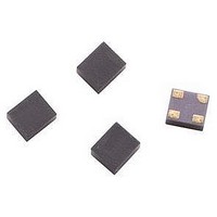
... MHz to 10 GHz frequency range. Note: 1. From the same PHEMT FET family, the smaller geometry ATF-34143 may also be considered for the higher gain performance, particularly in the higher frequency band (1.8 GHz and up). MiniPak 1 1.2 mm Package ...
Page 2
... ATF-331M4 Absolute Maximum Ratings Symbol Parameter [2] V Drain-Source Voltage DS [2] V Gate-Source Voltage GS [2] V Gate Drain Voltage GD [2] I Drain Current DS [4] P Total Power Dissipation diss P RF Input Power in max. [5] T Channel Temperature CH T Storage Temperature STG θ [6] Thermal Resistance jc 500 +0.6 V 400 ...
Page 3
... ATF-331M4 DC Electrical Specifications T = 25°C, RF parameters measured in a test circuit for a typical device A Symbol Parameter and Test Condition [1] Idss Saturated Drain Current [1] Vp Pinch-off Voltage Id Quiescent Bias Current [1] Gm Transconductance Igdo Gate to Drain Leakage Current Igss Gate Leakage Current NF Noise Figure ...
Page 4
... ATF-331M4 Typical Performance Curves 100 I (mA) ds [1] Figure 6. OIP3, IIP3 & Bias at 2 GHz 100 I (mA) dsq [1] Figure 9. P1dB vs. Bias 900 MHz. Notes: 1. Measurements made on fixed tuned production test board that was tuned for optimal gain match with reasonable noise figure bias. This circuit ...
Page 5
... ATF-331M4 Typical Performance Curves, continued 1.6 1.4 1.2 1.0 0.8 0.6 0.4 0 FREQUENCY (GHz) Figure 12. Fmin vs. Frequency mA 85°C 25°C 5 -40° FREQUENCY (GHz) Figure 15. P1dB, OIP3 vs. Frequency and Temp 4V, Ids = 60 mA. Notes: 1. Measurements made on fixed tuned production test board that was tuned for optimal gain match with reasonable noise figure bias ...
Page 6
... ATF-331M4 Typical Scattering Parameters, V Freq GHz Mag. Ang. dB 0.5 0.82 -91.90 22.10 0.8 0.79 -119.10 18.85 1.0 0.78 -132.10 18.06 1.5 0.76 -151.40 14.75 1.8 0.75 -159.60 13.55 2.0 0.74 -163.60 13.36 2.5 0.72 -170.70 10.33 3.0 0.69 -174.30 9.60 4.0 ...
Page 7
... ATF-331M4 Typical Scattering Parameters, V Freq GHz Mag. Ang. dB 0.5 0.82 -90.50 22.45 0.8 0.78 -117.70 19.31 1.0 0.77 -130.90 18.50 1.5 0.75 -150.40 15.23 1.8 0.74 -158.70 14.02 2.0 0.74 -162.70 13.79 2.5 0.72 -170.00 10.81 3.0 0.69 -174.10 9.60 4.0 ...
Page 8
... ATF-331M4 Typical Scattering Parameters, V Freq GHz Mag. Ang. dB 0.5 0.81 -93.60 22.93 0.8 0.78 -120.70 19.68 1.0 0.77 -133.60 18.81 1.5 0.75 -152.50 15.50 1.8 0.74 -160.50 14.27 2.0 0.74 -164.40 14.02 2.5 0.72 -171.30 11.06 3.0 0.70 -175.30 9.80 4.0 ...
Page 9
... ATF-331M4 Typical Scattering Parameters, V Freq GHz Mag. Ang. dB 0.5 0.82 -89.80 22.59 0.8 0.78 -116.90 19.49 1.0 0.77 -130.00 18.68 1.5 0.75 -149.70 15.42 1.8 0.74 -158.00 14.21 2.0 0.74 -162.20 13.70 2.5 0.72 -169.50 11.50 3.0 0.69 -173.80 10.20 4.0 ...
Page 10
... ATF-331M4 Typical Scattering Parameters, V Freq GHz Mag. Ang. dB 0.5 0.81 -93.00 23.11 0.8 0.78 -120.00 19.90 1.0 0.77 -133.00 19.03 1.5 0.75 -152.00 15.74 1.8 0.74 -160.00 14.50 2.0 0.74 -164.00 14.24 2.5 0.72 -171.00 11.29 3.0 0.69 -175.00 10.21 4.0 ...
Page 11
S and Noise Parameter Measurements The position of the reference planes used for the measurement of both S and Noise Parameter mea- surements is shown in Figure 23. The reference plane can be described as being at the center of ...
Page 12
... This model can be used as a design tool. It has been tested on ADS for various specifications. However, for more precise and accurate design, please refer to the measured data in this data sheet. For future improvements, Avago reserves the right to change these models without prior notice. ATF-331M4 Minipak Model INSIDE Package VAR ...
Page 13
... Ordering Information Part Number No. of Devices ATF-331M4-TR1 3000 ATF-331M4-TR2 10000 ATF-331M4-BLK 100 MiniPak Package Outline Drawing 1.44 (0.058) 1.40 (0.056) Px 1.20 (0.048) 1.16 (0.046) Top view 0.70 (0.028) 0.58 (0.023) Side view Dimensions are in millimeteres (inches) 13 Container 7” Reel 13” Reel ...
Page 14
Device Orientation for Outline 4T, MiniPak 1412 REEL CARRIER TAPE USER FEED DIRECTION COVER TAPE Tape Dimensions DESCRIPTION CAVITY LENGTH WIDTH DEPTH PITCH BOTTOM HOLE DIAMETER PERFORATION DIAMETER PITCH POSITION CARRIER TAPE WIDTH THICKNESS COVER TAPE ...