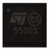
PD55003L-E STMicroelectronics, PD55003L-E Datasheet

PD55003L-E
Specifications of PD55003L-E
PD55003L-E
Available stocks
Related parts for PD55003L-E
PD55003L-E Summary of contents
Page 1
... Esd protection Supplied in tape & reel of 3K units In compliance with 2002/95/EC european directive Description The PD55003L common source N- Channel, enhancement-mode lateral Field-Effect RF power transistor designed for high gain, broadband commercial and industrial application. It operates at 12V in common source mode at frequencies 1GHz. PD5500L-E boasts ...
Page 2
Contents: 1 Electrical data . . . . . . . . . . . . . . . . . . . . . . . . . . . . . . . . . . . . ...
Page 3
Electrical data 1.1 Maximum Ratings Table 1. Absolute maximum ratings (T Symbol V Drain-Source Voltage (BR)DSS V Gate-Source Volatge GS Drain Current Power Dissipation (@T DISS T Storage Temperature stg T Operating Junction Temperature j 1.2 ...
Page 4
Electrical specification (T =25°C) CASE Table 3. Static Symbol Test Condictions I V DSS I V GSS V V GS( DS(ON iss C V =0V, V oss GS C rss Table 4. ...
Page 5
Figure 1. Typical Input/Drain load Impedances Table 7. Impedance Data FREQ. MHz 480 500 520 Typical Input Typical Drain Impedance Load Impedance G Zin S Z (Ω 4.96 1. 5.93 2.10 ...
Page 6
Typical performances Figure 2. Capacitance Vs supply Voltage (V) Figure 4. Power Gain Vs ...
Page 7
Figure 8. Efficiency Vs Bias Current 100 150 200 250 300 Idq (mA) Figure 10. Output Power Vs Gate-Source Voltage 0.0 ...
Page 8
Typical performance (broadband) Figure 11. Power Gain Vs Frequency (MHz ) Figure 13. Return Loss Vs Frequency ...
Page 9
Test circuit schematic VGG Table 8. Test Circuit Component List Component B1, B2 FERRIDE BEAD C1, C12 3000Pf, 100B ATC CHIP CAPACITOR C2, C3 15pF, 100B ATC ...
Page 10
Test Circuit 3.2 Test circuit photomaster 10/19 6.4 inches Rev1 ...
Page 11
... Table 9. S-Parameter (PD55003L) (V =12.5V, I =0.15A ∠Φ FREQ (MHz) 50 0.808 -110 100 0.772 -141 150 0.771 -152 200 0.779 -157 250 0.794 -161 300 0.809 -163 350 0.824 -165 400 0.839 -166 450 0.853 -168 500 0.865 -169 550 0.874 -171 600 0 ...
Page 12
... Table 10. S-Parameter (PD55003L) (V =12.5V, I =0.8A FREQ (MHz) 50 0.841 -124 100 0.800 -150 150 0.800 -159 200 0.803 -163 250 0.812 -166 300 0.822 -168 350 0.830 -169 400 0.837 -170 450 0.848 -172 500 0.857 -172 550 0.866 -174 600 0.874 ...
Page 13
... Table 11. S-Parameter (PD55003L) (V =12.5V, I =1.5A ∠Φ FREQ (MHz) 50 0.837 -114 100 0.799 -143 150 0.801 -154 200 0.809 -159 250 0.823 -163 300 0.835 -165 350 0.845 -167 400 0.855 -169 450 0.866 -170 500 0.876 -171 550 0.882 -173 600 0 ...
Page 14
Package mechanical data In order to meet environmental requirements, ST offers these devices in ECOPACK® packages. These packages have a Lead-free second level interconnect . The category of second level interconnect is marked on the package and on the ...
Page 15
Table 12. PowerFLAT™ Mechanical Data Dim. MIN 0.15 b 0. Figure 14. PowerFLAT™ Package Dimensions mm TYP. MAX. MIN. 0.90 1.00 0.02 0.05 0.24 0.25 ...
Page 16
Table 13. PowerFLAT™ Tape & Reel Dimensions DIM. MIN. Ao 5.15 Bo 5.15 Ko 1.0 Figure 15. PowerFLAT™ Tape & Reel 16/19 mm. TYP 5.25 5.25 1.1 Rev1 MAX. 5.35 5.35 1.2 ...
Page 17
Table 14. Recommended FOOTPRINT Rev1 17/19 ...
Page 18
Revision history Table 15. Document revision history Date Revision 14-Feb-2006 1 18/19 Changes First Issue Rev1 ...
Page 19
... No license is granted by implication or otherwise under any patent or patent rights of STMicroelectronics. Specifications mentioned in this publication are subject to change without notice. This publication supersedes and replaces all information previously supplied. STMicroelectronics products are not authorized for use as critical components in life support devices or systems without express written approval of STMicroelectronics ...


