MRF6S21100HR3 Freescale Semiconductor, MRF6S21100HR3 Datasheet
MRF6S21100HR3
Specifications of MRF6S21100HR3
Available stocks


Related parts for MRF6S21100HR3

MRF6S21100HR3 Summary of contents
Page 1
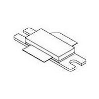
... MHz AVG CDMA LATERAL N - CHANNEL RF POWER MOSFETs CASE 465 - 06, STYLE 780 MRF6S21100HR3 CASE 465A - 06, STYLE 780S MRF6S21100HSR3 Symbol Value Unit V - 0.5, +68 Vdc DSS V - 0.5, +12 Vdc +150 °C stg T 150 ° 200 °C J (1,2) Symbol Value Unit R °C/W θJC 0.45 0.52 MRF6S21100HR3 MRF6S21100HSR3 1 ...
Page 2
... MHz Channel Bandwidth @ ±5 MHz Offset. IM3 measured in 3.84 MHz Channel Bandwidth @ ±10 MHz Offset. PAR = 8 0.01% Probability on CCDF. Power Gain Drain Efficiency Intermodulation Distortion Adjacent Channel Power Ratio Input Return Loss 1. Part is internally matched both on input and output. MRF6S21100HR3 MRF6S21100HSR3 2 = 25°C unless otherwise noted) C Symbol I DSS I ...
Page 3
... Microstrip Z4 0.093″ x 0.800″ Microstrip Z5 1.255″ x 0.040″ Microstrip Z6 0.160″ x 0.880″ Microstrip Figure 1. MRF6S21100HR3(SR3) Test Circuit Schematic Table 5. MRF6S21100HR3(SR3) Test Circuit Component Designations and Values Part B1 Ferrite Bead C1 1.0 μ Tantalum Capacitor C2 10 μ Electrolytic Capacitor ...
Page 4
... Figure 2. MRF6S21100HR3(SR3) Test Circuit Component Layout MRF6S21100HR3 MRF6S21100HSR3 C11 C12 C14 C9 C10 V DD C13 C7 2.1 GHz NI780 Rev 4 RF Device Data Freescale Semiconductor ...
Page 5
... Watts Avg. out 44 η −24 −10 −26 −20 −28 −30 −30 −40 2200 = 55 Watts Avg. out = 28 Vdc 2135 MHz 2145 MHz DD 1200 mA = 450 mA DQ 1450 mA 950 mA 700 OUTPUT POWER (WATTS) PEP out versus Output Power MRF6S21100HR3 MRF6S21100HSR3 100 5 ...
Page 6
... η OUTPUT POWER (WATTS) CW out Figure 10. Power Gain and Drain Efficiency versus CW Output Power MRF6S21100HR3 MRF6S21100HSR3 6 TYPICAL CHARACTERISTICS 100 28 Figure 8. Pulsed CW Output Power versus Vdc 950 2135 MHz 2145 MHz 2−Carrier W−CDMA, 10 MHz Carrier Spacing 3.84 MHz Channel Bandwidth PAR = 8 0.01% Probability (CCDF) ...
Page 7
... D 3.84 MHz Channel BW −ACPR in +ACPR in 3.84 MHz BW 3.84 MHz BW −IM3 in +IM3 in 3.84 MHz BW 3.84 MHz BW −20 −15 −10 − FREQUENCY (MHz) Figure 14. 2-Carrier W-CDMA Spectrum MRF6S21100HR3 MRF6S21100HSR3 ...
Page 8
... MHz Z Z Figure 15. Series Equivalent Source and Load Impedance MRF6S21100HR3 MRF6S21100HSR3 Ω load f = 2080 MHz f = 2200 MHz Z source f = 2080 MHz Vdc 950 mA Avg out source load MHz Ω Ω 2080 2.44 - j6.3 1.83 - j3.0 2110 2.25 - j6.1 1.74 - j2.8 2140 2 ...
Page 9
... Z4 0.090″ x 0.800″ Microstrip Z5 1.500″ x 0.040″ Microstrip Z6 0.160″ x 0.880″ Microstrip Figure 16. MRF6S21100HR3(SR3) Test Circuit Schematic — SCDMA Table 6. MRF6S21100HR3(SR3) Test Circuit Component Designations and Values — SCDMA Part B1 Ferrite Bead C1 1.0 μ Tantalum Capacitor C2 10 μ Electrolytic Capacitor ...
Page 10
... Figure 17. MRF6S21100HR3(SR3) Test Circuit Component Layout — SCDMA MRF6S21100HR3 MRF6S21100HSR3 C11 C14 C9 C10 V DD C13 C12 C7 2.1 GHz NI780 Rev 4 RF Device Data Freescale Semiconductor ...
Page 11
... Adj −U 9 Alt− 7.5 1.28 MHz Channel BW VBW = 300 kHz Sweep Time = 200 ms RBW = 30 kHz +ALT2 in 1.28 MHz BW +3.2 MHz Offset −ALT1 in +ALT1 in 1.28 MHz BW 1.28 MHz BW −1.6 MHz Offset +1.6 MHz Offset 2.5 MHz Span 25 MHz f, FREQUENCY (MHz) MRF6S21100HR3 MRF6S21100HSR3 11 ...
Page 12
... Figure 22. Series Equivalent Source and Load Impedance — SCDMA MRF6S21100HR3 MRF6S21100HSR3 Ω 2070 MHz Z load f = 1950 MHz Z source f = 1950 MHz f = 2070 MHz Vdc 800 source load MHz W W 1950 1.04 - j4.28 1.38 - j3.90 1960 1.07 - j4.31 1.41 - j3.92 1970 0.96 - j4.13 1 ...
Page 13
... REF 0.127 REF bbb 0.010 REF 0.254 REF ccc 0.015 REF 0.381 REF STYLE 1: PIN 1. DRAIN 2. GATE F 5. SOURCE MRF6S21100HR3 MRF6S21100HSR3 MAX 34.16 9.91 4.32 12.83 1.14 0.15 1.70 5.33 19.96 20.00 3.51 9.53 9.52 9.91 4.32 1.14 ...
Page 14
... MTTF calculator for device • Added TD - SCDMA test circuit schematic, component designations and values, component layout, typical characteristic curves, test signal and series impedance • Added Product Documentation and Revision History MRF6S21100HR3 MRF6S21100HSR3 14 PRODUCT DOCUMENTATION REVISION HISTORY ...
Page 15
... Freescale Semiconductor was negligent regarding the design or manufacture of the part. Freescalet and the Freescale logo are trademarks of Freescale Semiconductor, Inc. All other product or service names are the property of their respective owners. © Freescale Semiconductor, Inc. 2007. All rights reserved. MRF6S21100HR3 MRF6S21100HSR3 15 ...