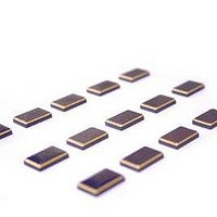
TR7001 RFM, TR7001 Datasheet - Page 4

TR7001
Manufacturer Part Number
TR7001
Description
RF Transceiver 3G ASH Transceiver 315 MHz 115.2 kbps
Manufacturer
RFM
Datasheet
1.TR7001.pdf
(15 pages)
Specifications of TR7001
Wireless Frequency
315 MHz
Output Power
10 mW
Mounting Style
SMD/SMT
Package / Case
SM3-20H
Modulation
OOK/ASK
Lead Free Status / RoHS Status
Lead free / RoHS Compliant
ASH Transceiver Theory of Operation
Introduction
RFM’s amplifier-sequenced hybrid (ASH) transceiver technology is specif-
ically designed for short-range wireless data communication applications.
ASH transceivers provide robust operation, very small size, low power
consumption and low implementation cost. All critical RF functions are
contained in the hybrid, simplifying and speeding design-in. ASH trans-
ceivers can be readily configured to support a wide range of data rates
and protocol requirements. These transceivers feature excellent suppres-
sion of transmitter harmonics and virtually no RF emissions when receiv-
ing, making them easy to certify to short-range (unlicensed) radio
regulations.
Amplifier-Sequenced Receiver Operation
The ASH transceiver’s unique feature set is made possible by its system
architecture. The heart of the transceiver is the amplifier-sequenced
receiver section, which provides more than 100 dB of stable RF and
detector gain without any special shielding or decoupling requirements.
Figure 1 shows the basic block diagram and timing cycle for an amplifier
sequenced receiver. Note that the bias to RF amplifiers RFA1 and RFA2
are independently controlled by a pulse generator, and that the two ampli-
fiers are coupled by a surface acoustic wave (SAW) delay line, which has
a typical delay of 0.5 µs.
RF Monolithics, Inc.
RFM Europe
©1999 by RF Monolithics, Inc. The stylized RFM logo are registered trademarks of RF Monolithics, Inc.
Phone: (972) 233-2903
Phone: 44 1963 251383
Delay Line
Out
RFA1 Out
RF Input
Antenna
P1
P2
t
PW1
t
PW2
ASH Receiver Block Diagram & Timing Cycle
SAW Filter
t
PRC
t
PRI
RFA1
Fax: (972) 387-8148
Fax: 44 1963 251510
P1
RF Data Pulse
Figure 1
Delay Line
Generator
Pulse
SAW
An incoming RF signal is first filtered by a narrow-band SAW filter, and is
then applied to RFA1. The pulse generator turns RFA1 ON for 0.814 µs.
The amplified signal from RFA1 emerges from the SAW delay line at the
input to RFA2. RFA1 is now switched OFF and RFA2 is switched ON for
0.814 µs, amplifying the RF signal further. The ON time for RFA1 and
RFA2 is set by a 614 kHz internal pulse generator. As shown in the timing
diagram, RFA1 and RFA2 are never on at the same time, assuring excel-
lent receiver stability. Note that the narrow-band SAW filter eliminates
sampling sideband responses outside of the receiver passband, and the
SAW filter and delay line act together to provide very high receiver ulti-
mate rejection.
ASH Transceiver Block Diagram
Figure 2 is the general block diagram of the ASH transceiver.
Please refer to Figure 2 for the following discussions.
Antenna Port
The only external RF components needed for the transceiver are the
antenna and its matching components. Antennas presenting an imped-
ance in the range of 35 to 72 ohms resistive can be satisfactorily matched
to the RFIO pin with a series matching coil and a shunt matching/ESD pro-
tection coil. Other antenna impedances can be matched using two or
three components. For some impedances, two inductors and a capacitor
will be required. A DC path from RFIOto ground is required for ESD pro-
tection.
RFA2
P2
Detector &
Low-Pass
Filter
E-mail: info@rfm.com
http://www.rfm.com
TR7001-11062007
Data
Out
Page 4 of 15


