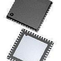
ATA5279-PLQW Atmel, ATA5279-PLQW Datasheet - Page 11

ATA5279-PLQW
Manufacturer Part Number
ATA5279-PLQW
Description
RF Wireless Misc High-end multiple antenna driver IC
Manufacturer
Atmel
Datasheet
1.ATA5279P-PLQW.pdf
(40 pages)
Specifications of ATA5279-PLQW
Package / Case
VQFN-48
Mounting Style
SMD/SMT
Lead Free Status / RoHS Status
Lead free / RoHS Compliant
Table 3-2.
9125L–RKE–03/11
Note:
Step
10
11
12
13
14
15
1
2
3
4
5
6
7
8
9
Steps 6, 10 and 14 are wait states, as the test structures need some time to stabilize in their new setting. This depends mainly
on the externally applied capacitors on the AxP and the AxN pins.
Get Driver Setup
Get Driver Setup
Get Driver Setup
Get Driver Setup
Get Driver Setup
Sequence for Example 1, Using the Diagnosis Mode
Set Coil Current
Set Coil Current
Set Coil Current
- no command -
- no command -
- no command -
Select Driver
Select Driver
Select Driver
Select Driver
Command
The suggested waiting time is calculated as follows:
The sequence above is an example of how the failure illustrated in
could be detected. Depending on the grade of detection detail that is required, a matrix for the
test sequence should be set up to find the most effective way of programming and testing. For
more details on the commands, please refer also to
Description” on page
t
diag,wait
=
I/O
O
O
O
O
O
I
I
I
I
I
I
I
I
I
I
I
I
2
----------------------------------------------------- -
V
S
300 µA
00101010 – 2Ah
10100001 – A1h
10100001 – A1h
00101010 – 2Ah
10100000 – A0h
00101001 – 29h
01101000 – 68h
00000001 – 01h
01101000 – 68h
00000010 – 02h
01101000 – 68h
00000010 – 02h
00101001 – 29h
01101000 – 68h
00001001 – 09h
01101000 – 68h
00000010 – 02h
C
Coding
e
21.
+
C
ant
Actions/Remarks
Selects driver 1 with Diagnosis Mode enabled
Reads back active driver info:
Channel 1 active, both lines return a 0
Selects driver 2 with Diagnosis Mode enabled
Reads back active driver info:
Channel 2 active, both lines return a 0
Closes test switches S_H2P and S_L2N
Note:
Wait for the test structures to stabilize in the new setting, see
below
Reads back active driver info:
Channel 2 active, but both lines return a 0
Selects driver 1 with Diagnosis Mode enabled
Closes test switches S_H1P and S_L1N (Note: S_L1P and
S_H1N are then open)
Wait for the test structures to stabilize in the new setting, see
below
Reads back active driver info:
Channel 1 active and A1P returns a 1
Selects driver 2 with Diagnosis Mode enabled
Closes test switches S_L2P and S_L2N
Note:
Wait for the test structures to stabilize in the new setting, see
below
Reads back active driver info:
Channel 2 active and A2P returns a 1
S_L2P and S_H2N are then open
S_H2P and S_H2N are then open
Section 3.9.2 “General Command
Atmel ATA5279
Figure 3-4 on page 10
11


