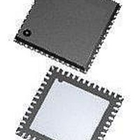
ATA5279-PLQW Atmel, ATA5279-PLQW Datasheet - Page 23

ATA5279-PLQW
Manufacturer Part Number
ATA5279-PLQW
Description
RF Wireless Misc High-end multiple antenna driver IC
Manufacturer
Atmel
Datasheet
1.ATA5279P-PLQW.pdf
(40 pages)
Specifications of ATA5279-PLQW
Package / Case
VQFN-48
Mounting Style
SMD/SMT
Lead Free Status / RoHS Status
Lead free / RoHS Compliant
9125L–RKE–03/11
Notes:
• Select Driver:
• The D
• Select Coil Current
• Send LF Data:
This command selects the coil that is to be driven or tested next. The BR-bit indicates the
modulation speed (0 for 3.9kbit/s, i.e., 32LF periods and 1 for 5.7kbit/s, i.e., 22LF periods).
for high-current driver 1..3, 1 for low-current driver 4..6) and D
group (01 for driver 1 / 4, 11 for driver 3 / 6). For connection line diagnosis, the diagnosis
mode can be enabled by setting the DM-bit to 1.
This command defines the current to be established for the next LF transmissions.
This command must be used to start an LF data telegram on the selected coil. The bits
N
ATA5279. This amount has to be coded as follows:
N
Hence, a maximum of 16 nibbles or eight words and a minimum of one nibble can be
written into the buffer using one command.
Note also that this command uses one more word of space in the buffer, as the header
word is also stored. So for example, if the LF telegram consists of four words, the required
space in the LF data buffer is five words (four words of pure data and one word for the
command header).
bit BR:
bit DM:
bits D
bit D
bits D
Default: D
speed selected.
bits C
bits C
whereas …
bit C
bit C
Default: C
3..0
3..0
1. If set, all coil connections are switched to this mode. Normal operation is not possible. (i.e.,
2. For a proper operation after a diagnosis run, a Reset Fault Status command also needs to
contain the amount of nibbles to be transferred into the LF data buffer of the Atmel
= (n
G
0
1
G,1..0
:
:
G,1..0
1..0
4..0
1
:
..C
LF transmission). The same works for the opposite way: once a Select Driver command is
received with the DM-bit at 0, all connection lines are switched back to normal operation
mode.
be sent.
Nibbles
:
:
0
4..0
:
G,1..0
bits indicate the channel number to be activated. D
:
= [00000] --> 50 mA coil current selected.
– 1)
LF modulator speed (0 for 3.9kbit/s, i.e., 32LF periods and 1 for 5.7kbit/s,
i.e., 22 LF periods, referred to Manchester coding)
Diagnosis mode selector (0: Normal LF operation mode, 1: Coil connection
diagnosis mode)
Active channel indicator
Driver group selector (0 for high-current driver 1..3, 1 for low-current driver
4..6)
Driver selector, i.e. 01 is driver 1 (D
(D
= [001], DM = 0, BR = 0 --> Channel 1, diagnosis mode off and normal LF
G
Contain the step number in the range of 0 to 19 (00hex to 13hex)
Are used in diagnosis mode, to control the test switches of the activated
connection line
The low/high-side switch of the AxP line
The low/high-side switch of the AxN line)
= 0) / 6 (D
G
= 1).
G
= 0) / 4 (D
Atmel ATA5279
1..0
G
G
selects the driver group (0
= 1), 11 is driver 3
the required driver in the
23


