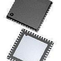
ATA5279-PLQW Atmel, ATA5279-PLQW Datasheet - Page 4

ATA5279-PLQW
Manufacturer Part Number
ATA5279-PLQW
Description
RF Wireless Misc High-end multiple antenna driver IC
Manufacturer
Atmel
Datasheet
1.ATA5279P-PLQW.pdf
(40 pages)
Specifications of ATA5279-PLQW
Package / Case
VQFN-48
Mounting Style
SMD/SMT
Lead Free Status / RoHS Status
Lead free / RoHS Compliant
3. Functional Description
3.1
4
Operation Modes
Atmel ATA5279
Atmel
Power-down mode is active after supply voltages have been applied to the chip. No internal
circuitry is active in this mode and as such power consumption is minimal. If no operation of
the chip is demanded, it should be kept in this state. To enter power-down mode, a negative
pulse on the NRES pin for at least t
After wake-up from power-down mode by a logic high signal at the S_CS pin, the chip is in idle
mode. That is, the oscillator is running and the control logic waits for commands coming from
the serial interface. Furthermore, the selected output driver stage is ready for operation (the
voltage on the corresponding output pin AxP is approximately half the battery supply voltage).
The current consumption of the chip is now mainly defined by the cross current through the
active driver stage (please refer also to
When processing coil driving commands, the chip is in operation mode. From the interface
point of view, there is no difference from the idle mode; however, current consumption is now
higher as the output driver stages are operating and, depending on the selected output cur-
rent, the DC-DC converter is also operating.
If a connection failure (short circuit on any of the coil connection lines) is detected, the
ATA5279 enters the shutdown mode to protect itself from damage. In this mode, the interface
operates in idle mode but with all power stages shutdown and no LF transmission command
processing. This mode should be exited using the Reset Fault Status command (see below),
however, it can also be exited by resetting the chip.
In diagnosis mode, the output driver stages are also disabled. In their place, high-ohmic cur-
rent sources are activated that can be programmed via the serial interface in order to check
the coil connection lines for failures. This mode can be exited by an appropriate SPI command
or by resetting the chip.
• Power-down mode (reset state)
• Idle mode
• Operating mode
• Shutdown mode
• Diagnosis mode
®
ATA5279 features five operation modes. They are:
NRES,min
Section 3.2 “Coil Driver Stage” on page
is required.
5).
9125L–RKE–03/11


