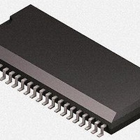
U4091BM-RFNY19 Atmel, U4091BM-RFNY19 Datasheet - Page 6

U4091BM-RFNY19
Manufacturer Part Number
U4091BM-RFNY19
Description
RF Wireless Misc COM.CORDED - FEATURE PHONE CIRCUIT
Manufacturer
Atmel
Type
Programmable Telephone Audio Processorr
Datasheet
1.U4091BM-RFNG3Y_19.pdf
(40 pages)
Specifications of U4091BM-RFNY19
Operating Frequency
100 KHz
Operating Temperature Range
- 55 C to +150 C
Package / Case
SSO-44
Mounting Style
SMD/SMT
Table 2-1.
3. DC Line Interface and Supply-voltage Generation
6
Note:
Pin
40
41
42
43
44
1. The protection device at pin RECIN is disconnected.
Atmel U4091BM-R
Pin Description
AMREC
Symbol
AMPB
STRC
STO
STC
Function
Input for playback signal of answering machine
Output for recording signal of answering machine
Output for connecting the sidetone network
Input for sidetone network
Input for sidetone network
The DC line interface consists of an electronic inductance and a dual-port output stage which
charges the capacitors at VMPS and VB. The value of the equivalent inductance is given by:
The U4091BM-R contains two identical series regulators which provide a supply voltage VMP
of 3.3V suitable for a microprocessor. In speech mode, both regulators are active because
VMPS and VB are charged simultaneously by the DC line interface. The output current is
6mA. The capacitor at VMPS is used to provide the microcomputer with sufficient power dur-
ing long line interruptions. Thus, long flash pulses can be bridged or an LCD display can be
turned on for more than 2 seconds after going on-hook. When the system is in ringing mode,
VB is charged by the on-chip ringing power converter. In this mode, only one regulator is used
to supply VMP with maximum 3mA.
L
=
2
------------------------------------------------------------------------------------------ -
×
R
SENSE
(
R
×
DC
C
IND
+
R
×
30
(
)
R
DC
×
R
30
)
4872B–CORD–01/11


