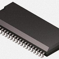
U4091BM-RFNY19 Atmel, U4091BM-RFNY19 Datasheet - Page 9

U4091BM-RFNY19
Manufacturer Part Number
U4091BM-RFNY19
Description
RF Wireless Misc COM.CORDED - FEATURE PHONE CIRCUIT
Manufacturer
Atmel
Type
Programmable Telephone Audio Processorr
Datasheet
1.U4091BM-RFNG3Y_19.pdf
(40 pages)
Specifications of U4091BM-RFNY19
Operating Frequency
100 KHz
Operating Temperature Range
- 55 C to +150 C
Package / Case
SSO-44
Mounting Style
SMD/SMT
8. Serial Bus Interface
8.1
8.2
4872B–CORD–01/11
WRITE
READ
The circuit is controlled by an external microcontroller through the serial bus.
The serial bus is a bi-directional system consisting of a single-directional clock line (SCL)
which is always driven by the microcontroller, and a bi-directional data-signal line. It is driven
by the microcontroller as well as by the Atmel
The serial bus requires external pull-up resistors as only pull-down transistors (pin SDA) are
integrated.
The data is a 12-bit word:
A0-A3: address of the destination register (0 to 15)
D0-D7: content of the register
The data line must be stable when the clock is high. Data must be shifted serially. After
12 clock periods, the write indication is sent. Then, the transfer to the destination register is
(internally) generated by a strobe signal transition of the data line when the clock is high.
There is a normal and a fast-read cycle.
In the normal read cycle, the microcontroller sends a 4-bit address followed by the read indica-
tor, then an 8-bit word is read out. The Atmel U4091BM-R drives the data line.
The fast read cycle is indicated by a strobe signal. With the following two clocks the Atmel
U4091BM-R reads out the status bits RFDO and LIDET which indicate that a ringing signal or
a line signal is present (see
on page
12).
Figure 10-1 on page
®
U4091BM-R (see
12,
Figure 10-2 on page 12
Atmel U4091BM-R
Figure 20-1 on page
and
Figure 10-3
38).
9


