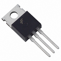
KSC5402DTTU Fairchild Semiconductor, KSC5402DTTU Datasheet

KSC5402DTTU
Specifications of KSC5402DTTU
Available stocks
Related parts for KSC5402DTTU
KSC5402DTTU Summary of contents
Page 1
... Thermal Characteristics Symbol R Thermal Resistance θJC R θJA T Maximum Lead Temperature for Soldering Purpose L ; 1/8” from Case for 5 Seconds * Mounted on 1” square PCB (FR4 ro G-10 Material) © 2009 Fairchild Semiconductor Corporation KSC5402D/KSC5402DT Rev =25°C unless otherwise noted A Parameter =25°C) : D-PAK TO-220 T =25° ...
Page 2
... DC Current Gain FE V (sat) Collector-Emitter Saturation CE Voltage V (sat) Base-Emitter Saturation BE Voltage C Input Capacitance ib C Output Capacitance ob f Current Gain Bandwidth T Product V Diode Forward Voltage F © 2009 Fairchild Semiconductor Corporation KSC5402D/KSC5402DT Rev =25°C unless otherwise noted A Test Condition I =1mA =5mA =1mA =1000V CES ...
Page 3
... Fall Time F t Cross-over Time C t Storage Time STG t Fall Time F t Cross-over Time C t Storage Time STG t Fall Time F t Cross-over Time C © 2009 Fairchild Semiconductor Corporation KSC5402D/KSC5402DT Rev. C0 (Continued) T =25°C unless otherwise noted A Test Condition I =0. =0. = =0.4A, I =40mA =300V CC ...
Page 4
... 1E-3 0.01 I [A], COLLECTOR CURRENT C Figure 3. DC current Gain =25 ℃ 0.1 1E-3 0.01 I [A], COLLECTOR CURRENT C Figure 5. Base-Emitter Saturation Voltage © 2009 Fairchild Semiconductor Corporation KSC5402D/KSC5402DT Rev 900mA 800mA 700mA 100 600mA 500mA 400mA 300mA 200mA 100mA 0.1 0.1 1 Figure 4 ...
Page 5
... I [A], COLLECTOR CURRENT C Figure 9. Typical Collector Saturation Region 10 1 =25 ℃ 0.1 0.01 0.1 I [A], CURRENT FD Figure 11. Diode Forward Voltage © 2009 Fairchild Semiconductor Corporation KSC5402D/KSC5402DT Rev. C0 (Continued) 1000 100 =125 ℃ 0.1 1 Figure 8. Collector Output Capacitance =25 ℃ 2.0A 1.5A 0.1 ...
Page 6
... =5I = =15V CC V =300V Z μ L =200 0.4 0.6 0.8 I [A], COLLECTOR CURRENT c Figure 17. Inductive Switching Time, t © 2009 Fairchild Semiconductor Corporation KSC5402D/KSC5402DT Rev. C0 (Continued) 850 I =5I = =300V CC μ PW=40 s 800 750 700 =125 ℃ 650 600 550 1.0 1.2 1.4 Figure 14 ...
Page 7
... I [A], COLLECTOR CURRENT c Figure 21. Inductive Switching Time 5ms 1 DC 0.1 0.01 10 100 V [V], COLLECTOR-EMITTER VOLTAGE CE Figure 23. Forward Bias Safe Operating Area © 2009 Fairchild Semiconductor Corporation KSC5402D/KSC5402DT Rev. C0 (Continued) 1.6 1.4 =125 ℃ T 1.2 J 1.0 =25 ℃ 0.8 0.6 1.0 1.2 1 ...
Page 8
... Physical Dimension © 2009 Fairchild Semiconductor Corporation KSC5402D/KSC5402DT Rev. C0 TO-220 9.90 ±0.20 (8.70) ø3.60 ±0.10 ±0.10 ±0.10 1.27 1.52 ±0.10 0.80 2.54TYP 2.54TYP [2.54 ±0.20 ] [2.54 ±0.20 ] ±0.20 10.00 8 4.50 ±0.20 +0.10 1.30 –0.05 +0.10 0.50 ±0.20 2.40 –0.05 Dimensions in Millimeters ...
Page 9
... Physical Dimension (Continued) © 2009 Fairchild Semiconductor Corporation KSC5402D/KSC5402DT Rev. C0 D-PAK 9 Dimensions in Millimeters www.fairchildsemi.com ...
Page 10
... TRADEMARKS The following includes registered and unregistered trademarks and service marks, owned by Fairchild Semiconductor and/or its global subsidiaries, and is not intended exhaustive list of all such trademarks. AccuPower FPS Auto-SPM F-PFS FRFET Build it Now CorePLUS Global Power Resource CorePOWER Green FPS CROSSVOLT Green FPS CTL™ ...


