2SD1760TLP Rohm Semiconductor, 2SD1760TLP Datasheet - Page 2
2SD1760TLP
Manufacturer Part Number
2SD1760TLP
Description
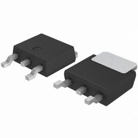
TRANS DVR NPN 50V 3A SOT-428 TR
Manufacturer
Rohm Semiconductor
Datasheet
1.2SD1760TLR.pdf
(3 pages)
Specifications of 2SD1760TLP
Transistor Type
NPN
Current - Collector (ic) (max)
3A
Voltage - Collector Emitter Breakdown (max)
50V
Vce Saturation (max) @ Ib, Ic
1V @ 200mA, 2A
Dc Current Gain (hfe) (min) @ Ic, Vce
82 @ 500mA, 3V
Power - Max
15W
Frequency - Transition
90MHz
Mounting Type
Surface Mount
Package / Case
DPak, TO-252 (2 leads+tab), SC-63
Lead Free Status / RoHS Status
Lead free / RoHS Compliant
Current - Collector Cutoff (max)
-


Transistors
! ! ! ! Electrical characteristics (Ta=25°C)
! ! ! ! Packaging specifications and h
! ! ! ! Electrical characteristic curves
∗ Measured using pulse current.
Type
2SD1760
2SD1864
Collector-base breakdown voltage
Collector-emitter breakdown voltage
Emitter-base breakdown voltage
Collector cutoff current
Emitter cutoff current
Collector-emitter saturation voltage
DC current transfer ratio
Transition frequency
Output capacitance
Fig.1 Grounded emitter propagation
1000
0.05
0.02
0.01
500
200
100
0.5
0.2
0.1
10
20
10
50
5
2
1
5
2
1
0.01 0.02 0.05 0.1 0.2 0.5
0
Fig.4 DC current gain vs.
BASE TO EMITTER VOLTAGE : V
Ta = 100°C
0.2 0.4 0.6 0.8 1.0 1.2 1.4 1.6 1.8
characteristics
COLLECTOR CURRENT : I
−25°C
25°C
Parameter
h
PQR
PQR
collector current( Ι )
FE
Package
Code
Basic ordering
unit (pieces)
1
2
V
Ta = 25°C
C
3V
V
CE
(A)
CE
= 5V
BE
= 3V
5
(V)
Symbol
10
V
BV
BV
BV
FE
I
CE (sat)
Cob
I
2500
h
CBO
EBO
f
TL
FE
T
CBO
CEO
EBO
−
Taping
1000
3.0
2.5
2.0
1.5
1.0
0.5
Fig.2 Grounded emitter output
500
200
100
20
10
COLLECTOR TO EMITTER VOLTAGE : V
50
0
0
5
2
1
0.01 0.02 0.05 0.1 0.2
Min.
60
50
82
Ta = 25°C
5
−
−
−
−
−
2500
45mA
50mA
TV2
Fig.5 DC current gain vs.
−
COLLECTOR CURRENT : I
characteristics ( Ι )
1
Typ.
0.5
90
40
−
−
−
−
−
−
Ta = 100°C
collector curren( ΙΙ )
2
Max.
390
−25°C
−
−
−
1
1
1
−
−
25°C
0.5
3
h
MHz
Unit
40mA
1
µA
µA
pF
FE
V
V
V
V
−
35mA
30mA
values are classified as follows:
2
25mA
Item
C
4
V
h
20mA
I
(A)
CE
B
FE
= 0mA
15mA
10mA
I
I
I
V
V
I
V
V
V
= 3V
C
C
E
C
5mA
5
CB
EB
CE
CE
CB
=50µA
=1mA
=50µA
/I
CE
B
=4V
=40V
=3V, I
=5V, I
=10V, I
=2A/0.2A
10
5
( V)
C
E
82~180
=0.5A
=−500mA, f=30MHz
E
=0A, f=1MHz
0.05
0.02
0.01
P
0.5
0.2
0.1
Fig.6 Collector-emitter saturation
3.0
2.5
2.0
1.5
1.0
0.5
10
Conditions
5
2
1
0.010.02 0.05 0.1 0.2
COLLECTOR TO EMITTER VOLTAGE : V
0
0
Fig.3 Grounded-emitter output
I
C
2SD1760 / 2SD1864
/I
B
20mA
COLLECTOR CURRENT : I
= 50
15mA
voltage vs. collector current
10
20
10
120~270
characteristics( ΙΙ )
Q
10mA
50mA
45mA
40mA
35mA
30mA
25mA
20
I
B
P
= 5mA
0.5
C
∗
∗
∗
= 15W
180~390
30
1
R
2
Ta = 25°C
C
Ta = 25°C
40
(A)
5
CE
10
50
(V)
Related parts for 2SD1760TLP
Image
Part Number
Description
Manufacturer
Datasheet
Request
R

Part Number:
Description:
Manufacturer:
Rohm Semiconductor
Datasheet:
Part Number:
Description:
Manufacturer:
Rohm Semiconductor
Datasheet:
Part Number:
Description:
Manufacturer:
Rohm Semiconductor
Datasheet:
Part Number:
Description:
Manufacturer:
Rohm Semiconductor
Datasheet:
Part Number:
Description:
Manufacturer:
Rohm Semiconductor
Datasheet:
Part Number:
Description:
Manufacturer:
Rohm Semiconductor
Datasheet:
Part Number:
Description:
Manufacturer:
Rohm Semiconductor
Datasheet:
Part Number:
Description:
Manufacturer:
Rohm Semiconductor
Datasheet:
Part Number:
Description:
Manufacturer:
Rohm Semiconductor
Datasheet:
Part Number:
Description:
Manufacturer:
Rohm Semiconductor
Datasheet:
Part Number:
Description:
Manufacturer:
Rohm Semiconductor
Datasheet:
Part Number:
Description:
Manufacturer:
Rohm Semiconductor
Datasheet:

Part Number:
Description:
DIODE SWITCH 80V 25MA SMD5 TR
Manufacturer:
Rohm Semiconductor
Datasheet: