8-1393792-5 TE Connectivity, 8-1393792-5 Datasheet - Page 414
8-1393792-5
Manufacturer Part Number
8-1393792-5
Description
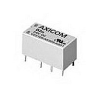
Electromechanical Relay DPDT 3A 5VDC 168Ohm Through Hole
Manufacturer
TE Connectivity
Type
Signal Relayr
Specifications of 8-1393792-5
Contact Arrangement
DPDT
Dc Coil Voltage
5 V
Coil Current
29.76 mA
Mounting
Through Hole
Relay Construction
Non-Latching
Coil Voltage Dc
5V
Contact Form
2 Form C
Voltage Rating (vdc)
220V
Voltage Rating (vac)
250V
Dropout Volt (min)
0.25VDCV
Coil Resistance
168Ohm
Pick-up Voltage (max)
4VDC
Maximum Power Rating
60W/125VA
Operate Time
5ms
Contact Current Rating
3A
Contact Material
AgNi/Au
Coil Suppression Diode
No
Push To Test Button
No
Led Indicator
No
Seal
Unsealed
Product Height (mm)
11mm
Product Depth (mm)
10mm
Product Length (mm)
20.2mm
Operating Temp Range
-25C to 85C
Pin Count
8
Mounting Style
Through Hole
Termination Style
PC Pin
Package / Case
DIP
Lead Free Status / Rohs Status
Compliant


1214
Mounting Clip Dimensions
SSA-24C667
Mouting Clip
DIP Switch Layout
Interval On (Input Controlled)
initiated at the same time with the relay de-energizing at the completion of the time interval.
state of the relay.
Recycler (Initially On)
power. The initial state of the relay will be energized.
inhibit timing until it is once again opened, at which time it will start from zero time.
2.283
(58.0)
Delay on Operate
by the application of input voltage.
energize the relay and reset the timer. Opening the switch will initiate another time interval.
Closing the control switch during timing will reset the time to zero and inhibit timing until
opened again.
Recycler (Initially Off)
power. The initial state of the relay will be de-energized.
and inhibit timing until it is once again opened, at which time it will start from zero time.
Note: The solid black blocks in the DIP switch diagrams indicate the switch positions. For
Timing Function Descriptions and Switch Settings
Dimensions are shown for
reference purposes only.
8 Or 11 Pin
1
1
72 & 92 - Output relay will begin cycling at a 50% duty cycle with the application of input
76 & 96 - Same as the above except, closing the control switch will energize the relay and
1
1
72 & 92 - Output relay will begin cycling at a 50% duty cycle with the application of input
76 & 96 - Same as the above except, closing the control switch will de-energize the relay
72 & 92 - Output relay is energized by the application of input voltage. The time interval is
76 & 96 - Same as above. Closing the control switch will have no effect on timing or the
72 & 92 - Output relay is energized at the completion of the time interval which is initiated
76 & 96 - Same as the above except, closing the control switch after time out will de-
2.047
(52.0)
example, all the switches are “off” in the diagram above.
(50.0)
1.970
2
2
2
2
On
3
3
3
3
1
(42.0)
(48.0)
1.654
1.890
4
4
4
4
Function
2
Setting
3
(15.0)
.591
4
Dimensions are in inches over
(millimeters) unless otherwise
specified.
5
Setting
Time
6
7
Catalog 1308242
Issued 3-03
Timing Range Switch Settings
11 Pin Only
Interval On (Switch Controlled)
closed or the closing of the control switch with the input applied. Immediately upon either,
timing is initiated with the relay de-energizing at the completion of the time interval. Closing the
control switch after time out will reset the timer, energize the relay, and initiate another time
interval. Closing the control switch during timing will have no effect on timing or the state of the
relay.
Delay on Release
or the application of input voltage with the control switch already closed. The time interval will
be initiated by the opening of the control switch with the relay de-energizing at the completion
of the time interval. Closing the control switch after time out will energize the relay in
preparation for another time interval. Closing the control switch during timing will reset the
time to zero and inhibit timing until opened again.
Inverted Delay on Release
control switch is open. Control switch closing will de-energize the relay. A timing interval will
be initiated with the opening of the control switch, at the completion of which the relay
willenergize. With the control switch closed upon application of input voltage, the relay will
wait until the control switch is opened to initiate a time interval after which the relay will
energize. Closing of the control switch during timing will reset the time to zero and inhibit
timing until opened again.
Interval Off
the control switch is open. Control switch closing will de-energize the relay and start a time
interval. At the completion of the time interval, the relay will energize. With the control switch
closed upon application of input voltage, a time interval will be initiated after which the relay will
energize. Closing of the control switch during timing will have no effect on timing or the state
of the relay.
76 & 96 - Output relay is energized by the closing of the control switch with the input applied
1
1
1
76 & 96 - Output relay will initially be energized with the application of the input voltage when
5
5
5
1
76 & 96 - Output relay is energized by the application of input voltage with the control switch
72 & 92 - No Time Delay - Instantly On
76 & 96 - Output relay will energize with the application of the input voltage when the
DIP Switch
Setting
2
6
6
6
2
2
2
Specifications and availability
subject to change.
7
7
7
3
3
3
3
0.1 - 1.0 Second
1.0 - 10 Seconds
10 - 100 Seconds
4
Timing Range
4
4
4
5
5
5
DIP Switch
Setting
6
6
6
7
7
7
www.tycoelectronics.com
Technical support:
Refer to inside back cover.
0.1 - 1.0 Minute
1.0 - 10 Minutes
10 - 100 Minutes
Timing Range
P&B
Related parts for 8-1393792-5
Image
Part Number
Description
Manufacturer
Datasheet
Request
R

Part Number:
Description:
FFC / FPC Connectors 4 13 CONDUCTOR .100 Polyester
Manufacturer:
Tyco Electronics

Part Number:
Description:
#8 PRE-INSUL SEALED SPLICE
Manufacturer:
TE Connectivity
Datasheet:

Part Number:
Description:
TERMINAL,SOLIS R 8 8
Manufacturer:
TE Connectivity
Datasheet:

Part Number:
Description:
TERMINAL, RING TONGUE 3/8IN CRIMP YELLOW
Manufacturer:
TE Connectivity
Datasheet:

Part Number:
Description:
TERMINAL, RING TONGUE, #8, CRIMP, YELLOW
Manufacturer:
TE Connectivity
Datasheet:
Part Number:
Description:
TERMINAL, RING TONGUE, 3/8IN, CRIMP
Manufacturer:
TE Connectivity
Datasheet:
Part Number:
Description:
TERMINAL, RING TONGUE, #8, CRIMP, YELLOW
Manufacturer:
TE Connectivity
Datasheet:

Part Number:
Description:
TERMINAL,R PG 8 1/4
Manufacturer:
TE Connectivity
Datasheet:

Part Number:
Description:
TERMINAL, SPADE/FORK, #8, CRIMP, YELLOW
Manufacturer:
TE Connectivity
Datasheet:
Part Number:
Description:
TERMINAL, RING TONGUE, #8, CRIMP, YELLOW
Manufacturer:
TE Connectivity
Datasheet:

Part Number:
Description:
Manufacturer:
TE Connectivity
Datasheet:


Part Number:
Description:
Manufacturer:
TE Connectivity
Datasheet:

Part Number:
Description:
SOCKET, D, R/A, 9WAY, 4-40UNC
Manufacturer:
TE Connectivity
Datasheet:
Part Number:
Description:
Electromechanical Relay SPDT 15A 12VDC 400Ohm Through Hole
Manufacturer:
TE Connectivity
Datasheet: