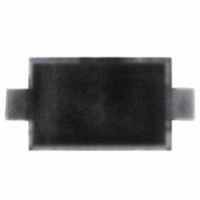
BBY 58-02V E6327 Infineon Technologies, BBY 58-02V E6327 Datasheet

BBY 58-02V E6327
Specifications of BBY 58-02V E6327
SP000012231
Related parts for BBY 58-02V E6327
BBY 58-02V E6327 Summary of contents
Page 1
Silicon Tuning Diodes Excellent linearity High Q hyperabrupt tuning diode Low series resistance Designed for low tuning voltage operation for VCO's in mobile communications equipment For low frequency control elements such as TCXOs and VCXOs Very low capacitance spread Pb-free ...
Page 2
Electrical Characteristics at T Parameter DC Characteristics Reverse current ° Characteristics Diode capacitance MHz ...
Page 3
Diode capacitance 1MHz 0.5 1 1.5 2 2.5 Temperature coefficient of the diode capacitance 1/°C ...
Page 4
Package Outline Foot Print Marking Layout (Example) Standard Packing Reel ø180 mm = 3.000 Pieces/Reel Reel ø180 mm = 8.000 Pieces/Reel (2 mm Pitch) Reel ø330 mm = 10.000 Pieces/Reel Standard 4 0.4 Cathode marking 0.93 Package SC79 0.2 M ...
Page 5
Package Outline Cathode marking Foot Print Marking Layout (Example) Standard Packing Reel ø180 mm = 3.000 Pieces/Reel Reel ø180 mm = 8.000 Pieces/Reel (2 mm Pitch) Reel ø330 mm = 10.000 Pieces/Reel Standard 4 Cathode marking Package SCD80 0.2 A ...
Page 6
Date Code marking for discrete packages with one digit (SCD80, SC79, SC75 Month ...
Page 7
Package Outline Foot Print Marking Layout (Example) Standard Packing Reel ø180 mm = 3.000 Pieces/Reel Reel ø330 mm = 10.000 Pieces/Reel Cathode marking Package SOD323 +0.2 0.9 -0.1 +0.2 1.25 0 -0.1 ±0.05 2 Cathode marking 1 +0.1 0.3 -0.05 ...
Page 8
Package Outline Foot Print Marking Layout (Example) Standard Packing Reel ø180 mm = 3.000 Pieces/Reel Reel ø330 mm = 10.000 Pieces/Reel Package SOT323 2 ±0.2 0.1 MAX. +0.1 3x 0.3 -0.05 0 0.65 0.65 0.2 0.6 ...
Page 9
Package Outline Top view 2 1 Cathode marking 1) Dimension applies to plated terminal Foot Print For board assembly information please refer to Infineon website "Packages" Copper Marking Layout (Example) Standard Packing Reel ø180 mm = 15.000 Pieces/Reel Reel ø330 ...
Page 10
... For information on the types in question please contact your nearest Infineon Technologies Office. Infineon Technologies Components may only be used in life-support devices or systems with the express written approval of Infineon Technologies failure of such components can reasonably be expected to cause the failure of that life-support device or system affect the safety or effectiveness of that device or system ...


