103308-8 TE Connectivity, 103308-8 Datasheet - Page 2
103308-8
Manufacturer Part Number
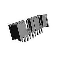
103308-8
Description
Conn Shrouded Header HDR 40 POS 2.54mm Solder ST Thru-Hole
Manufacturer
TE Connectivity
Type
Shrouded Headerr
Specifications of 103308-8
Pitch
2.54 mm
Number Of Rows
2
Number Of Contacts
40
Gender
HDR
Contact Plating
Gold Over Nickel/Gold Over Palladium Nickel
Termination Method
Solder
Product Line
AMP-LATCH
Profile
Low
Pcb Mounting Orientation
Vertical
Pcb Mount Retention
Without
Mating Connector Lock
Without
Housing Style
4-Sided
Ejection Latches
Without
Post Size (mm [in])
0.64 [.025]
Shrouded
Yes
[shrouded] End Dimension (mm [in])
3.81 [0.150]
Current Rating (a)
1
Insulation Resistance (m?)
5,000
Termination Post Length (mm [in])
3.05 [0.120]
Solder Tail Contact Plating
Tin-Lead over Nickel
Header Type
Pin Header
Number Of Positions
40
Centerline, Matrix (mm [in])
2.54 x 2.54 [.100 x .100]
Daisy Chain
With
Preloaded
Yes
Contact Plating, Mating Area, Material
Gold (15), Gold Flash over Palladium Nickel
Contact Shape
Square
Contact Base Material
Copper Alloy
Connector Style
Header - Pin
Mating Alignment Type
Center, Dual Polarizing Bar
Mating Alignment
With
Housing Material
Thermoplastic - GF
Ul Flammability Rating
UL 94V-0
Housing Color
Black
Rohs/elv Compliance
ELV compliant, 5 of 6 Compliant
Lead Free Solder Processes
Not suitable for lead free processing
Approved Standards
UL E28476, CSA LR7189
Operating Temperature (°c)
-65 – +105
Temperature Rating
Standard
Available stocks
Company
Part Number
Manufacturer
Quantity
Price
Company:

Part Number:
103308-8
Manufacturer:
TE
Quantity:
49 434
Company:
Part Number:
103308-8
Manufacturer:
ERNI
Quantity:
35 000


3.2.
3.3.
3.4.
3.5.
Exam ination of product.
Term ination resistance, dry circuit.
Insulation resistance.
Dielectric withstanding voltage.
Random vibration.
Rev D
Material
Materials used in the construction of this product shall be as specified on the applicable product
drawing.
Ratings
!
!
Perform ance and Test Description
Product is designed to m eet the electrical, m echanical and environm ental perform ance requirem ents
specified in Figure 1. Unless otherwise specified, all tests are perform ed at am bient environm ental
conditions per Test Specification 109-1.
Test Requirem ents and Procedures Sum m ary
Test Description
Current: 1 am pere m axim um (single circuit energized), see Para 3.5.(b)
Operating tem perature:
NOTE
Continuous current rating for individual contacts cannot be applied directly to the number
of contacts as they are dependent on thermal and physical properties of the materials.
System design shall assure that continuous current rating does not create internal hot
spots that exceed temperature designated by connector specification during steady state
or transient conditions.
15 m illiohm s m axim um .
Meets requirem ents of product
drawing and Application
Specification 114-40005.
5000 m egohm s m inim um initial.
1000 m egohm s m inim um final after
hum idity/tem perature cycling.
One m inute hold with no breakdown
or flashover.
No discontinuity greater than 1
m icrosecond.
See Note (a).
-65 to 105 C, unless lim ited by tem perature rating of cable used
Figure 1 (continued)
MECHANICAL
ELECTRICAL
Requirem ent
TE Spec 109-6-1.
Visual, dim ensional and functional
per applicable quality inspection
plan.
Subject m ated contacts assem bled
in housing to 50 m illivolt open circuit
at 100 m illiam peres.
See Figure 3.
TE Spec 109-28-4.
Test between adjacent contacts
within a row and contacts in
adjacent row of unm ated and
unterm inated connectors.
TE Spec 109-29-1.
1000 volts DC at sea level.
Test between adjacent contacts
within a row and contacts in
adjacent row of unm ated and
unterm inated connectors.
TE Spec 109-21-5, Test level G.
Subject wired and m ated
connectors to 23.91 Gs rm s, 20
m inutes each plane.
See Figure 4.
Procedure
108-40000
2 of 6
Related parts for 103308-8
Image
Part Number
Description
Manufacturer
Datasheet
Request
R

Part Number:
Description:
Conn Shrouded Header HDR 10 POS 2.54mm Solder ST Thru-Hole
Manufacturer:
TE Connectivity
Datasheet:

Part Number:
Description:
Conn Shrouded Header HDR 14 POS 2.54mm Solder ST Thru-Hole
Manufacturer:
TE Connectivity
Datasheet:
Part Number:
Description:
Conn Shrouded Header HDR 16 POS 2.54mm Solder ST Thru-Hole
Manufacturer:
TE Connectivity
Datasheet:

Part Number:
Description:
Conn Shrouded Header HDR 26 POS 2.54mm Solder ST Thru-Hole
Manufacturer:
TE Connectivity
Datasheet:
Part Number:
Description:
Conn Shrouded Header HDR 20 POS 2.54mm Solder ST Thru-Hole
Manufacturer:
TE Connectivity
Datasheet:

Part Number:
Description:
High Speed / Modular Connectors 30P HEADER ASSY
Manufacturer:
TE Connectivity
Datasheet:

Part Number:
Description:
High Speed / Modular Connectors REC 6X005P R/A LT B-PLANE HS3
Manufacturer:
TE Connectivity
Datasheet:

Part Number:
Description:
High Speed / Modular Connectors 2MM HM RCPT 50P R/A AU
Manufacturer:
TE Connectivity
Datasheet:

Part Number:
Description:
High Speed / Modular Connectors 2MM HM RCPT 50P R/A AU
Manufacturer:
TE Connectivity
Datasheet:


Part Number:
Description:
Manufacturer:
TE Connectivity
Datasheet:


Part Number:
Description:
Manufacturer:
TE Connectivity
Datasheet:

Part Number:
Description:
Manufacturer:
TE Connectivity
Datasheet:

Part Number:
Description:
Manufacturer:
TE Connectivity
Datasheet: