104130-5 TE Connectivity, 104130-5 Datasheet - Page 23
104130-5
Manufacturer Part Number
104130-5
Description
Conn Ejector Header HDR 26 POS 2.54mm Solder RA Thru-Hole
Manufacturer
TE Connectivity
Type
Ejector Headerr
Series
AMP-LATCHr
Datasheet
1.1-102618-8.pdf
(320 pages)
Specifications of 104130-5
Pitch
2.54 mm
Number Of Rows
2
Number Of Contacts
26
Gender
HDR
Contact Plating
Gold Over Nickel
Termination Method
Solder
Connector Type
Wire To Board
Contact Termination
Right Angle Through Hole
No. Of Contacts
26
No. Of Rows
2
Pitch Spacing
2.54mm
Rohs Compliant
No
Product Line
AMP-LATCH
Profile
Low
Pcb Mounting Orientation
Right Angle
Pcb Mount Retention
Without
Mating Connector Lock
Without
Housing Style
4-Sided
Ejection Latches
With
Post Size (mm [in])
0.64 [.025]
Shrouded
Yes
[shrouded] End Dimension (mm [in])
3.81 [0.150]
Current Rating (a)
1
Insulation Resistance (m?)
5,000
Termination Post Length (mm [in])
3.43 [0.135]
Solder Tail Contact Plating
Tin-Lead over Nickel
Header Type
Pin Header
Number Of Positions
26
Centerline, Matrix (mm [in])
2.54 x 2.54 [.100 x .100]
Daisy Chain
With
Preloaded
Yes
Contact Plating, Mating Area, Material
Gold (30), Gold Flash over Palladium Nickel
Contact Shape
Square
Contact Base Material
Copper Alloy
Connector Style
Header - Pin
Mating Alignment Type
Center, Dual Polarizing Bar
Mating Alignment
With
Housing Material
Thermoplastic - GF
Ul Flammability Rating
UL 94V-0
Housing Color
Black
Rohs/elv Compliance
Not ELV/RoHS compliant
Lead Free Solder Processes
Not suitable for lead free processing
Approved Standards
UL E28476, CSA LR7189
Operating Temperature (°c)
-65 – +105
Temperature Rating
Standard


Catalog 1307819
Revised 8-08
www.tycoelectronics.com
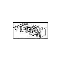
The Manual Miniature
Application Frame
Assembly 91295-1,
equipped with a Cover
Closing Kit 543518-1, is
used for the IDC termina-
tion of ribbon cable to the
cable connectors shown on
page 21.
Prior to termination, the
covers must be partially
assembled onto a connec-
tor housing, the cable
inserted between the cov-
ers and contacts and the
covers preclosed by hand,
clamping the cable in
place.
In the Manual Miniature
Application Frame
Assembly, the covers are
fully seated to complete the
mass termination and pro-
vide strain relief for the
completed connection.
For tooling information, call
Technical Support Center
1-800-522-6752.
Note: Refer to Tyco Electonics
Instruction Sheets 408-9817 (Frame
Assembly 91295-1) and 408-9909
(Cover Closing Kit 543518-1) for
complete termination/tooling infor-
mation.
are metric equivalents.
Dimensions are in inches and
millimeters unless otherwise
specified. Values in brackets
AMPMODU Interconnection System
Application Tooling for Cable Connectors
Note: All part numbers are RoHS compliant.
Dimensions are shown for
reference purposes only.
Specifications subject
to change.
Manual Miniature Application Frame Assembly 91295-1
with Cover Closing Kit 543518-1
USA: 1-800-522-6752
Canada: 1-905-470-4425
Mexico: 01-800-733-8926
C. America: 52-55-1106-0803
South America: 55-11-2103-6000
Hong Kong: 852-2735-1628
Japan: 81-44-844-8013
UK: 44-8706-080-208
23
2
Related parts for 104130-5
Image
Part Number
Description
Manufacturer
Datasheet
Request
R

Part Number:
Description:
Conn Ejector Header HDR 10 POS 2.54mm Solder RA Thru-Hole
Manufacturer:
TE Connectivity
Datasheet:

Part Number:
Description:
Conn Ejector Header HDR 16 POS 2.54mm Solder RA Thru-Hole
Manufacturer:
TE Connectivity
Datasheet:
Part Number:
Description:
Conn Ejector Header HDR 20 POS 2.54mm Solder RA Thru-Hole
Manufacturer:
TE Connectivity
Datasheet:
Part Number:
Description:
WIRE-BOARD CONN, HEADER, 14POS, 2.54MM
Manufacturer:
TE Connectivity
Datasheet:
Part Number:
Description:
WIRE-BOARD CONN, HEADER, 34POS, 2.54MM
Manufacturer:
TE Connectivity

Part Number:
Description:
High Speed / Modular Connectors 30P HEADER ASSY
Manufacturer:
TE Connectivity
Datasheet:

Part Number:
Description:
High Speed / Modular Connectors REC 6X005P R/A LT B-PLANE HS3
Manufacturer:
TE Connectivity
Datasheet:

Part Number:
Description:
High Speed / Modular Connectors 2MM HM RCPT 50P R/A AU
Manufacturer:
TE Connectivity
Datasheet:

Part Number:
Description:
High Speed / Modular Connectors 2MM HM RCPT 50P R/A AU
Manufacturer:
TE Connectivity
Datasheet:


Part Number:
Description:
Manufacturer:
TE Connectivity
Datasheet:


Part Number:
Description:
Manufacturer:
TE Connectivity
Datasheet:

Part Number:
Description:
Manufacturer:
TE Connectivity
Datasheet:

Part Number:
Description:
Manufacturer:
TE Connectivity
Datasheet: