PIC16F1519-E/P Microchip Technology, PIC16F1519-E/P Datasheet - Page 195
PIC16F1519-E/P
Manufacturer Part Number
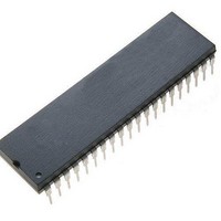
PIC16F1519-E/P
Description
40-pin, 28KB Flash, 1024B RAM, 10-bit ADC, 2xCCP, SPI, MI2C, EUSART, 2.3V-5.5V 4
Manufacturer
Microchip Technology
Series
PIC® XLP™ 16Fr
Datasheet
1.PIC16F1516-EMV.pdf
(344 pages)
Specifications of PIC16F1519-E/P
Processor Series
PIC16F151x
Core
PIC
Data Bus Width
8 bit
Program Memory Type
Flash
Program Memory Size
16 KB
Data Ram Size
1 KB
Interface Type
I2C, SPI, USART
Maximum Clock Frequency
20 MHz
Number Of Programmable I/os
36
Number Of Timers
3
Operating Supply Voltage
2.3 V to 5.5 V
Maximum Operating Temperature
+ 125 C
Mounting Style
Through Hole
Package / Case
PDIP-40
Core Processor
PIC
Core Size
8-Bit
Speed
20MHz
Connectivity
I²C, LIN, SPI, UART/USART
Peripherals
Brown-out Detect/Reset, POR, PWM, WDT
Number Of I /o
36
Eeprom Size
-
Ram Size
1K x 8
Voltage - Supply (vcc/vdd)
2.3 V ~ 5.5 V
Data Converters
A/D 28x10b
Oscillator Type
Internal
Operating Temperature
-40°C ~ 125°C
Lead Free Status / Rohs Status
Details
Available stocks
Company
Part Number
Manufacturer
Quantity
Price
Company:

Part Number:
PIC16F1519-E/PT
Manufacturer:
Microchip Technology
Quantity:
10 000


21.2.6
In SPI Master mode, module clocks may be operating
at a different speed than when in Full-Power mode; in
the case of the Sleep mode, all clocks are halted.
Special care must be taken by the user when the MSSP
clock is much faster than the system clock.
In Slave mode, when MSSP interrupts are enabled,
after the master completes sending data, an MSSP
interrupt will wake the controller from Sleep.
If an exit from Sleep mode is not desired, MSSP inter-
rupts should be disabled.
TABLE 21-1:
2011 Microchip Technology Inc.
ANSELA
ANSELC
APFCON
INTCON
PIE1
PIR1
SSPBUF
SSPCON1
SSPCON3
SSPSTAT
TRISA
TRISA
Legend:
Name
*
SPI OPERATION IN SLEEP MODE
— = Unimplemented location, read as ‘0’. Shaded cells are not used by the MSSP in SPI mode.
Page provides register information.
Synchronous Serial Port Receive Buffer/Transmit Register
TMR1GIE
TMR1GIF
ACKTIM
TRISA7
TRISC7
ANSC7
WCOL
Bit 7
SMP
GIE
—
—
SUMMARY OF REGISTERS ASSOCIATED WITH SPI OPERATION
TRISC6
SSPOV
TRISA6
ANSC6
ADIE
PCIE
Bit 6
PEIE
ADIF
CKE
—
—
TMR0IE
TRISC5
SSPEN
TRISA5
ANSA5
ANSC5
RCIE
RCIF
SCIE
Bit 5
D/A
—
TRISA4
TRISC4
ANSC4
BOEN
Preliminary
INTE
TXIE
Bit 4
TXIF
CKP
—
—
P
TRISA3
TRISC3
ANSA3
ANSC3
SDAHT
SSPIE
SSPIF
IOCIE
Bit 3
In SPI Master mode, when the Sleep mode is selected,
all module clocks are halted and the transmis-
sion/reception will remain in that state until the device
wakes. After the device returns to Run mode, the mod-
ule will resume transmitting and receiving data.
In SPI Slave mode, the SPI Transmit/Receive Shift
register operates asynchronously to the device. This
allows the device to be placed in Sleep mode and data
to be shifted into the SPI Transmit/Receive Shift
register. When all 8 bits have been received, the MSSP
interrupt flag bit will be set and if enabled, will wake the
device.
—
S
PIC16(L)F1516/7/8/9
TMR0IF
CCP1IE
CCP1IF
TRISC2
SBCDE
TRISA2
ANSA2
ANSC2
Bit 2
R/W
—
SSPM<3:0>
TMR2IE
TMR2IF
TRISA1
TRISC1
ANSA1
SSSEL
AHEN
Bit 1
INTF
UA
—
CCP2SEL
TMR1IE
TMR1IF
TRISC0
TRISA0
ANSA0
DHEN
IOCIF
Bit 0
DS41452B-page 195
BF
—
Register
on Page
189*
124
233
235
233
123
117
114
116
80
81
83
Related parts for PIC16F1519-E/P
Image
Part Number
Description
Manufacturer
Datasheet
Request
R

Part Number:
Description:
IC, 8BIT MCU, PIC16F, 32MHZ, SOIC-18
Manufacturer:
Microchip Technology
Datasheet:

Part Number:
Description:
IC, 8BIT MCU, PIC16F, 32MHZ, SSOP-20
Manufacturer:
Microchip Technology
Datasheet:

Part Number:
Description:
IC, 8BIT MCU, PIC16F, 32MHZ, DIP-18
Manufacturer:
Microchip Technology
Datasheet:

Part Number:
Description:
IC, 8BIT MCU, PIC16F, 32MHZ, QFN-28
Manufacturer:
Microchip Technology
Datasheet:

Part Number:
Description:
IC, 8BIT MCU, PIC16F, 32MHZ, QFN-28
Manufacturer:
Microchip Technology
Datasheet:
Part Number:
Description:
IC, 8BIT MCU, PIC16F, 32MHZ, QFN-28
Manufacturer:
Microchip Technology
Datasheet:
Part Number:
Description:
IC, 8BIT MCU, PIC16F, 32MHZ, SSOP-20
Manufacturer:
Microchip Technology
Datasheet:

Part Number:
Description:
IC, 8BIT MCU, PIC16F, 20MHZ, DIP-40
Manufacturer:
Microchip Technology
Datasheet:

Part Number:
Description:
IC, 8BIT MCU, PIC16F, 32MHZ, QFN-28
Manufacturer:
Microchip Technology
Datasheet:

Part Number:
Description:
IC, 8BIT MCU, PIC16F, 20MHZ, MQFP-44
Manufacturer:
Microchip Technology
Datasheet:

Part Number:
Description:
IC, 8BIT MCU, PIC16F, 20MHZ, QFN-20
Manufacturer:
Microchip Technology
Datasheet:
Part Number:
Description:
IC, 8BIT MCU, PIC16F, 32MHZ, QFN-28
Manufacturer:
Microchip Technology
Datasheet:

Part Number:
Description:
MCU 14KB FLASH 768B RAM 64-TQFP
Manufacturer:
Microchip Technology
Datasheet:
Part Number:
Description:
7 KB Flash, 384 Bytes RAM, 32 MHz Int. Osc, 16 I/0, Enhanced Mid Range Core, Low
Manufacturer:
Microchip Technology

Part Number:
Description:
14KB Flash, 512B RAM, 256B EEPROM, LCD, 1.8-5.5V 40 UQFN 5x5x0.5mm TUBE
Manufacturer:
Microchip Technology
Datasheet: