PIC16LF1507-E/SS Microchip Technology, PIC16LF1507-E/SS Datasheet - Page 190
PIC16LF1507-E/SS
Manufacturer Part Number
PIC16LF1507-E/SS
Description
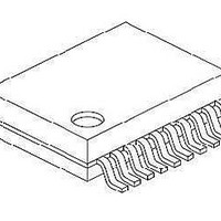
3.5KB Flash, 128B RAM, 18 I/O, CLC, CWG, DDS, 10-bit ADC 20 SSOP .209in TUBE
Manufacturer
Microchip Technology
Series
PIC® 16Fr
Datasheet
1.PIC16F1507-EML.pdf
(266 pages)
Specifications of PIC16LF1507-E/SS
Processor Series
PIC16
Core
PIC16F
Data Bus Width
8 bit
Program Memory Type
Flash
Program Memory Size
3.5 KB
Data Ram Size
128 B
Interface Type
ICSP
Maximum Clock Frequency
20 MHz
Number Of Programmable I/os
18
Number Of Timers
3
Operating Supply Voltage
2.3 V to 5.5 V
Maximum Operating Temperature
+ 125 C
Mounting Style
SMD/SMT
Package / Case
SSOP-20
Minimum Operating Temperature
- 40 C
Operating Temperature Range
- 40 C to + 125 C
Supply Current (max)
30 uA
Core Processor
PIC
Core Size
8-Bit
Speed
20MHz
Connectivity
-
Peripherals
Brown-out Detect/Reset, POR, PWM, WDT
Number Of I /o
17
Eeprom Size
-
Ram Size
128 x 8
Voltage - Supply (vcc/vdd)
1.8 V ~ 3.6 V
Data Converters
A/D 12x10b
Oscillator Type
Internal
Operating Temperature
-40°C ~ 125°C
Lead Free Status / Rohs Status
Details
Available stocks
Company
Part Number
Manufacturer
Quantity
Price

Part Number:
PIC16LF1507-E/SS
Manufacturer:
MICROCHIP/微芯
Quantity:
20 000


22.1
The CWG generates a two output complementary
waveform from one of four selectable input sources.
The off-to-on transition of each output can be delayed
from the on-to-off transition of the other output, thereby,
creating a time delay immediately where neither output
is driven. This is referred to as dead time and is covered
in Section 22.5 “Dead-Band Control”. A typical
operating waveform, with dead band, generated from a
single input signal is shown in
It may be necessary to guard against the possibility of
circuit faults or a feedback event arriving too late or not
at all. In this case, the active drive must be terminated
before the Fault condition causes damage. This is
referred to as auto-shutdown and is covered in
Section 22.9 “Auto-shutdown Control”.
22.2
The CWG module allows for up to 2 different clock
sources to be selected:
• Fosc (system clock)
• HFINTOSC (16 MHz only)
The clock sources are selected using the G1CS0 bit of
the CWGxCON0 register
22.3
The CWG uses four different input sources to gener-
ate the complementary waveform:
• PWM1
• PWM2
• PWM3
• PWM4
• N1OUT
• LC1OUT
The input sources are selected using the GxIS<2:0>
bits in the CWGxCON1 register
22.4
Immediately after the CWG module is enabled, the
complementary drive is configured with both CWGxA
and CWGxB drives cleared.
22.4.1
Each CWG output pin has individual output enable
control. Output enables are selected with the GxOEA
and GxOEB bits of the CWGxCON0 register. When an
output enable control is cleared, the module asserts no
control over the pin. When an output enable is set, the
override value or active PWM waveform is applied to
the pin per the port priority selection. The output pin
enables are dependent on the module enable bit,
GxEN. When GxEN is cleared, CWG output enables
and CWG drive levels have no effect.
2011 Microchip Technology Inc.
Fundamental Operation
Clock Source
Selectable Input Sources
Output Control
OUTPUT ENABLES
(Register
Figure
(Register
22-1).
22-2.
22-2).
Preliminary
22.4.2
The polarity of each CWG output can be selected
independently. When the output polarity bit is set, the
corresponding output is active high. Clearing the output
polarity bit configures the corresponding output as
active low. However, polarity does not affect the
override levels. Output polarity is selected with the
GxPOLA and GxPOLB bits of the CWGxCON0 register.
22.5
Dead-band control provides for non-overlapping output
signals to prevent shoot through current in power
switches. The CWG contains two 6-bit dead-band
counters. One dead-band counter is used for the rising
edge of the input source control. The other is used for
the falling edge of the input source control.
Dead band is timed by counting CWG clock periods
from zero up to the value in the rising or falling dead-
band
CWGxDBF registers
respectively).
22.6
The rising edge dead-band delays the turn-on of the
CWGxA output from when the CWGxB output is turned
off. The rising edge dead-band time starts when the
rising edge of the input source signal goes true. When
this happens, the CWGxB output is immediately turned
off and the rising edge dead-band delay time starts.
When the rising edge dead-band delay time is reached,
the CWGxA output is turned on.
The CWGxDBR register sets the duration of the dead-
band interval on the rising edge of the input source
signal. This duration is from 0 to 64 counts of dead band.
Dead band is always counted off the edge on the input
source signal. A count of 0 (zero), indicates that no
dead band is present.
If the input source signal is not present for enough time
for the count to be completed, no output will be seen on
the respective output.
counter
Dead-Band Control
Rising Edge Dead Band
POLARITY CONTROL
PIC16(L)F1507
registers.
(Register 22-4
See
DS41586A-page 190
and
CWGxDBR
Register
22-5,
and
Related parts for PIC16LF1507-E/SS
Image
Part Number
Description
Manufacturer
Datasheet
Request
R

Part Number:
Description:
IC, 8BIT MCU, PIC16LF, 32MHZ, QFN-28
Manufacturer:
Microchip Technology
Datasheet:

Part Number:
Description:
IC, 8BIT MCU, PIC16LF, 32MHZ, QFN-28
Manufacturer:
Microchip Technology
Datasheet:

Part Number:
Description:
IC, 8BIT MCU, PIC16LF, 32MHZ, DIP-18
Manufacturer:
Microchip Technology
Datasheet:

Part Number:
Description:
IC, 8BIT MCU, PIC16LF, 20MHZ, TQFP-44
Manufacturer:
Microchip Technology
Datasheet:
Part Number:
Description:
7 KB Flash, 384 Bytes RAM, 32 MHz Int. Osc, 16 I/0, Enhanced Mid Range Core, Nan
Manufacturer:
Microchip Technology

Part Number:
Description:
14KB Flash, 512B RAM, LCD, 11x10b ADC, EUSART, NanoWatt XLP 28 SOIC .300in T/R
Manufacturer:
Microchip Technology
Datasheet:
Part Number:
Description:
14KB Flash, 512B RAM, LCD, 11x10b ADC, EUSART, NanoWatt XLP 28 SSOP .209in T/R
Manufacturer:
Microchip Technology
Datasheet:
Part Number:
Description:
MCU PIC 14KB FLASH XLP 28-SSOP
Manufacturer:
Microchip Technology
Part Number:
Description:
MCU PIC 14KB FLASH XLP 28-SOIC
Manufacturer:
Microchip Technology
Part Number:
Description:
MCU PIC 512B FLASH XLP 28-UQFN
Manufacturer:
Microchip Technology
Part Number:
Description:
MCU PIC 14KB FLASH XLP 28-SPDIP
Manufacturer:
Microchip Technology

Part Number:
Description:
MCU 7KB FLASH 256B RAM 40-UQFN
Manufacturer:
Microchip Technology
Part Number:
Description:
MCU 7KB FLASH 256B RAM 44-TQFP
Manufacturer:
Microchip Technology

Part Number:
Description:
MCU 14KB FLASH 1KB RAM 28-UQFN
Manufacturer:
Microchip Technology
Part Number:
Description:
MCU PIC 14KB FLASH XLP 40-UQFN
Manufacturer:
Microchip Technology