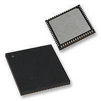
PIC18F65K90T-I/MR Microchip Technology, PIC18F65K90T-I/MR Datasheet - Page 563

PIC18F65K90T-I/MR
Manufacturer Part Number
PIC18F65K90T-I/MR
Description
32kB Flash, 2kB RAM, 1kB EE, NanoWatt XLP, LCD 64 QFN 9x9x0.9mm T/R
Manufacturer
Microchip Technology
Series
PIC® XLP™ 18Fr
Datasheet
1.PIC18F66K90-IMR.pdf
(570 pages)
Specifications of PIC18F65K90T-I/MR
Processor Series
PIC18F
Core
PIC
Data Bus Width
8 bit
Program Memory Type
Flash
Program Memory Size
32 KB
Data Ram Size
2 KB
Interface Type
I2C, SPI
Maximum Clock Frequency
64 MHz
Number Of Timers
8
Operating Supply Voltage
1.8 V to 5.5 V
Maximum Operating Temperature
+ 125 C
3rd Party Development Tools
52715-96, 52716-328, 52717-734, 52712-325, EWPIC18
Minimum Operating Temperature
- 40 C
On-chip Adc
12 bit, 16 Channel
Core Processor
PIC
Core Size
8-Bit
Speed
64MHz
Connectivity
I²C, LIN, SPI, UART/USART
Peripherals
Brown-out Detect/Reset, LCD, POR, PWM, WDT
Number Of I /o
53
Eeprom Size
1K x 8
Ram Size
2K x 8
Voltage - Supply (vcc/vdd)
1.8 V ~ 5.5 V
Data Converters
A/D 16x12b
Oscillator Type
Internal
Operating Temperature
-40°C ~ 85°C
Package / Case
64-VFQFN Exposed Pad
Lead Free Status / Rohs Status
Details
- Current page: 563 of 570
- Download datasheet (5Mb)
2009-2011 Microchip Technology Inc.
CMSTAT (Comparator Status).................................. 391
CMxCON (Comparator Control x)............................. 390
CONFIG1H (Configuration 1 High) ........................... 428
CONFIG1L (Configuration 1 Low)............................. 427
CONFIG2H (Configuration 2 High) ........................... 430
CONFIG2L (Configuration 2 Low)............................. 429
CONFIG3H (Configuration 3 High) ........................... 431
CONFIG3L (Configuration 3 Low)............................. 431
CONFIG4L (Configuration 4 Low)............................. 432
CONFIG5H (Configuration 5 High) ........................... 434
CONFIG5L (Configuration 5 Low)............................. 433
CONFIG6H (Configuration 6 High) ........................... 436
CONFIG6L (Configuration 6 Low)............................. 435
CONFIG7H (Configuration 7 High) ........................... 438
CONFIG7L (Configuration 7 Low)............................. 437
CTMUCONH (CTMU Control High) .......................... 408
CTMUCONL (CTMU Control Low)............................ 409
CTMUICON (CTMU Current Control) ....................... 410
CVRCON (Comparator Voltage Reference
DAY (Day Value)....................................................... 224
DEVID1 (Device ID 1) ............................................... 439
DEVID2 (Device ID 2) ............................................... 439
ECCPxAS (ECCPx Auto-Shutdown Control) ............ 265
ECCPxDEL (Enhanced PWM Control) ..................... 268
EECON1 (Data EEPROM Control 1) ........................ 122
EECON1 (EEPROM Control 1)................................. 113
HLVDCON (High/Low-Voltage Detect Control)......... 401
HOUR (Hour Value) .................................................. 225
INTCON (Interrupt Control)....................................... 131
INTCON2 (Interrupt Control 2).................................. 132
INTCON3 (Interrupt Control 3).................................. 133
IPR1 (Peripheral Interrupt Priority 1)......................... 145
IPR2 (Peripheral Interrupt Priority 2)......................... 146
IPR3 (Peripheral Interrupt Priority 3)......................... 147
IPR4 (Peripheral Interrupt Priority 4)......................... 147
IPR5 (Peripheral Interrupt Priority 5)......................... 148
IPR6 (Peripheral Interrupt Priority 6)......................... 149
LCDCON (LCD Control)............................................ 274
LCDDATAx (LCD Datax) .......................................... 279
LCDPS (LCD Phase) ................................................ 275
LCDREF (LCD Reference Voltage Control).............. 276
LCDRL (LCD Reference Ladder Control) ................. 277
LCDSEx (LCD Segmentx Enable) ............................ 278
MINUTE (Minute Value)............................................ 225
MONTH (Month Value) ............................................. 223
ODCON1 (Peripheral Open-Drain Control 1)............ 154
ODCON2 (Peripheral Open-Drain Control 2)............ 155
ODCON3 (Peripheral Open-Drain Control 3)............ 156
OSCCON (Oscillator Control) ..................................... 43
OSCCON2 (Oscillator Control 2) ........................ 44, 204
OSCTUNE (Oscillator Tuning) .................................... 45
PADCFG1 (Pad Configuration)................................. 220
PIE1 (Peripheral Interrupt Enable 1)......................... 140
PIE2 (Peripheral Interrupt Enable 2)......................... 141
PIE3 (Peripheral Interrupt Enable 3)......................... 142
PIE4 (Peripheral Interrupt Enable 4)......................... 142
PIE5 (Peripheral Interrupt Enable 5)......................... 143
PIE6 (Peripheral Interrupt Enable 6)......................... 144
PIR1 (Peripheral Interrupt Request (Flag) 1) ............ 134
PIR2 (Peripheral Interrupt Request (Flag) 2) ............ 135
PIR3 (Peripheral Interrupt Request (Flag) 3) ............ 136
PIR4 (Peripheral Interrupt Request (Flag) 4) ............ 137
PIR5 (Peripheral Interrupt Request (Flag) 5) ............ 138
PIR6 (Peripheral Interrupt Request (Flag) 6) ............ 139
Control) ............................................................. 397
PIC18F87K90 FAMILY
RESET.............................................................................. 481
Reset .................................................................................. 69
Resets .............................................................................. 425
RETFIE ............................................................................. 482
RETLW ............................................................................. 482
RETURN........................................................................... 483
Return Address Stack......................................................... 87
Return Stack Pointer (STKPTR) ......................................... 88
Revision History................................................................ 553
RLCF ................................................................................ 483
RLNCF.............................................................................. 484
RRCF................................................................................ 484
RRNCF ............................................................................. 485
PMD0 (Peripheral Module Disable 0) ......................... 64
PMD1 (Peripheral Module Disable 1) ......................... 63
PMD2 (Peripheral Module Disable 2) ......................... 62
PMD3 (Peripheral Module Disable 3) ......................... 61
PSTRxCON (Pulse Steering Control) ....................... 269
RCON (Reset Control)........................................ 70, 150
RCSTAx (Receive Status and Control) .................... 351
REFOCON (Reference Oscillator Control) ................. 51
Reserved .................................................................. 222
RTCCAL (RTCC Calibration).................................... 220
RTCCFG (RTCC Configuration)............................... 219
SECOND (Second Value) ........................................ 225
SSPxCON1 (MSSPx Control 1, I
SSPxCON1 (MSSPx Control 1, SPI Mode).............. 305
SSPxCON2 (MSSPx Control 2, I
SSPxCON2 (MSSPx Control 2, I
SSPxMSK (I
SSPxSTAT (MSSPx Status, I
SSPxSTAT (MSSPx Status, SPI Mode) ................... 304
STATUS ................................................................... 103
STKPTR (Stack Pointer)............................................. 88
T0CON (Timer0 Control) .......................................... 183
T1CON (Timer1 Control) .......................................... 187
T1GCON (Timer1 Gate Control)............................... 188
T2CON (Timer2 Control) .......................................... 199
TxCON (Timer3/5/7 Control) .................................... 202
TxCON (Timer4/6/8/10/12 Control) .......................... 214
TxGCON (Timer3/5/7 Gate Control) ......................... 203
TXSTAx (Transmit Status and Control) .................... 350
WDTCON (Watchdog Timer Control) ....................... 441
WEEKDAY (Weekday Value) ................................... 224
YEAR (Year Value)................................................... 223
Brown-out Reset (BOR).............................................. 69
Configuration Mismatch (CM)..................................... 69
MCLR Reset, Normal Operation................................. 69
MCLR Reset, Power-Managed Modes....................... 69
Power-on Reset (POR)............................................... 69
RESET Instruction ...................................................... 69
Stack Full.................................................................... 69
Stack Underflow ......................................................... 69
State of Registers ....................................................... 74
Watchdog Timer (WDT).............................................. 69
Brown-out Reset (BOR)............................................ 425
Oscillator Start-up Timer (OST)................................ 425
Power-on Reset (POR)............................................. 425
Power-up Timer (PWRT) .......................................... 425
2
C Slave Address Mask, 7-Bit) ............. 317
2
C Mode).................... 314
2
2
2
C Mode) .............. 315
C Master Mode) .. 316
C Slave Mode) .... 317
DS39957D-page 563
Related parts for PIC18F65K90T-I/MR
Image
Part Number
Description
Manufacturer
Datasheet
Request
R

Part Number:
Description:
Manufacturer:
Microchip Technology Inc.
Datasheet:

Part Number:
Description:
Manufacturer:
Microchip Technology Inc.
Datasheet:

Part Number:
Description:
Manufacturer:
Microchip Technology Inc.
Datasheet:

Part Number:
Description:
Manufacturer:
Microchip Technology Inc.
Datasheet:

Part Number:
Description:
Manufacturer:
Microchip Technology Inc.
Datasheet:

Part Number:
Description:
Manufacturer:
Microchip Technology Inc.
Datasheet:

Part Number:
Description:
Manufacturer:
Microchip Technology Inc.
Datasheet:

Part Number:
Description:
Manufacturer:
Microchip Technology Inc.
Datasheet:


