PIC18LF13K22-E/ML Microchip Technology, PIC18LF13K22-E/ML Datasheet - Page 251
PIC18LF13K22-E/ML
Manufacturer Part Number
PIC18LF13K22-E/ML
Description
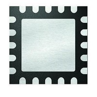
8KB Flash, 256bytes RAM, 256bytes EEPROM, 16MIPS, NanoWatt XLP 20 QFN 4x4mm TUBE
Manufacturer
Microchip Technology
Series
PIC® XLP™ 18Fr
Datasheets
1.PIC18LF13K22-ISS.pdf
(388 pages)
2.PIC18LF13K22-ISS.pdf
(12 pages)
3.PIC18LF13K22-ISS.pdf
(36 pages)
Specifications of PIC18LF13K22-E/ML
Core Processor
PIC
Core Size
8-Bit
Speed
48MHz
Connectivity
I²C, LIN, SPI, UART/USART
Peripherals
Brown-out Detect/Reset, POR, PWM, WDT
Number Of I /o
17
Program Memory Size
8KB (4K x 16)
Program Memory Type
FLASH
Eeprom Size
256 x 8
Ram Size
256 x 8
Voltage - Supply (vcc/vdd)
1.8 V ~ 3.6 V
Data Converters
A/D 12x10b
Oscillator Type
Internal
Operating Temperature
-40°C ~ 125°C
Package / Case
20-VQFN Exposed Pad, 20-HVQFN, 20-SQFN, 20-DHVQFN
Processor Series
PIC18LF
Core
PIC
Data Bus Width
8 bit
Data Ram Size
256 B
Interface Type
EUSART, I2C, SPI
Maximum Clock Frequency
32 KHz
Number Of Programmable I/os
18
Number Of Timers
4
Operating Supply Voltage
1.8 V to 3.6 V
Maximum Operating Temperature
+ 125 C
Mounting Style
SMD/SMT
3rd Party Development Tools
52715-96, 52716-328, 52717-734, 52712-325, EWPIC18
Development Tools By Supplier
PG164130, DV164035, DV244005, DV164005
Minimum Operating Temperature
- 40 C
On-chip Adc
10 bit, 12 Channel
A/d Bit Size
10 bit
A/d Channels Available
12
Height
0.88 mm
Length
4 mm
Supply Voltage (max)
3.6 V
Supply Voltage (min)
1.8 V, 2.7 V
Width
4 mm
Lead Free Status / RoHS Status
Lead free / RoHS Compliant
Lead Free Status / RoHS Status
Lead free / RoHS Compliant


21.2
The MCLR pin provides a method for triggering an
external Reset of the device. A Reset is generated by
holding the pin low. These devices have a noise filter in
the MCLR Reset path which detects and ignores small
pulses.
The MCLR pin is not driven low by any internal Resets,
including the WDT.
In PIC18F1XK22/LF1XK22 devices, the MCLR input
can be disabled with the MCLRE Configuration bit.
When MCLR is disabled, the pin becomes a digital
input. See Section 8.1 “PORTA, TRISA and LATA
Registers” for more information.
21.3
A Power-on Reset pulse is generated on-chip
whenever V
allows the device to start in the initialized state when
V
To take advantage of the POR circuitry, tie the MCLR
pin through a resistor (1 k to 10 k) to V
eliminate external RC components usually needed to
create a Power-on Reset delay.
When the device starts normal operation (i.e., exits the
Reset condition), device operating parameters (volt-
age, frequency, temperature, etc.) must be met to
ensure operation. If these conditions are not met, the
device must be held in Reset until the operating
conditions are met.
POR events are captured by the POR bit of the RCON
register. The state of the bit is set to ‘0’ whenever a
POR occurs; it does not change for any other Reset
event. POR is not reset to ‘1’ by any hardware event.
To capture multiple events, the user must manually set
the bit to ‘1’ by software following any POR.
2010 Microchip Technology Inc.
DD
is adequate for operation.
Master Clear (MCLR)
Power-on Reset (POR)
DD
rises above a certain threshold. This
DD
. This will
Preliminary
PIC18F1XK22/LF1XK22
FIGURE 21-2:
Note 1: External Power-on Reset circuit is required
V
2: R < 40 k is recommended to make sure that
3: R1 1 k will limit any current flowing into
DD
D
only if the V
The diode D helps discharge the capacitor
quickly when V
the voltage drop across R does not violate
the device’s electrical specification.
MCLR from external capacitor C, in the event
of MCLR/V
Electrostatic Discharge (ESD) or Electrical
Overstress (EOS).
V
DD
R
C
EXTERNAL POWER-ON
RESET CIRCUIT (FOR
SLOW V
DD
PP
R1
DD
power-up slope is too slow.
pin breakdown, due to
powers down.
DD
MCLR
PIC
DS41365D-page 251
POWER-UP)
®
MCU
Related parts for PIC18LF13K22-E/ML
Image
Part Number
Description
Manufacturer
Datasheet
Request
R

Part Number:
Description:
Manufacturer:
Microchip Technology Inc.
Datasheet:
Part Number:
Description:
Manufacturer:
Microchip Technology Inc.
Datasheet:
Part Number:
Description:
Manufacturer:
Microchip Technology Inc.
Datasheet:
Part Number:
Description:
Manufacturer:
Microchip Technology Inc.
Datasheet:
Part Number:
Description:
Manufacturer:
Microchip Technology Inc.
Datasheet:
Part Number:
Description:
Manufacturer:
Microchip Technology Inc.
Datasheet:
Part Number:
Description:
Manufacturer:
Microchip Technology Inc.
Datasheet:
Part Number:
Description:
Manufacturer:
Microchip Technology Inc.
Datasheet: