CUB50000 Red Lion Controls, CUB50000 Datasheet - Page 3
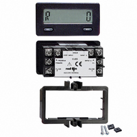
CUB50000
Manufacturer Part Number
CUB50000
Description
COUNTER/RATE INDICATOR RELFECT
Manufacturer
Red Lion Controls
Series
CUB5r
Datasheet
1.CUB50000.pdf
(8 pages)
Specifications of CUB50000
Count Rate
20kHz
Number Of Digits/alpha
8
Input Type
Voltage
Voltage - Supply
9 V ~ 28 V
Display Type
LCD Non-Backlit
Lead Free Status / RoHS Status
Lead free / RoHS Compliant
Output Type
-
Other names
Q517088
RLC500
RLC500


PROGRAMMING GENERAL DESCRIPTION
unit has been programmed at the factory, the parameters generally have to be
changed to meet the user’s requirements. To enter the programming mode,
connect the program terminal to the common terminal.
flashes between the menu and the currently selected data. Pressing the reset
button stops the display from flashing and enters the unit into the data
modification mode.
program.
1. Selection type - The operator presses the reset button to scroll through the
2. Numerical type - The reset button increments the numerical value of the
the programming mode, remove the connection between the Program terminal
and the Common terminal. If power is removed from the CUB5 prior to exiting
the programming mode, the new data is not saved.
PROGRAMMING MENUS
1. COUNT MODES (INP A-b)
function of Input A and Input B and assigns the function to either COUNTER
A, COUNTER B, RATE INDICATOR or a combination of the three. The user
input terminal programmed for the inhibit function, can be used with any of the
count modes. Input A is always assigned to the RATE INDICATOR.
Programming the CUB5 is done with the front panel buttons. Although the
Pressing the select button scrolls through the menus. The display alternately
In the data modification mode, a menu has one of two types of parameters to
various parameters available for that menu or to toggle between a Yes or No
selection. Pressing and holding the Select button exits the data modification
mode and advances to the next menu.
flashing digit. Momentarily pressing the Select button advances to the next
digit. Pressing and holding the Select button for more than two seconds exits
the data modification mode and advances to the next menu.
All parameter values are saved when exiting the programming mode. To exit
There are eight count modes to select from. This selection determines the
Counting with Direction (cnt ud)
Rate Counter (rtE cnt)
Dual Counter (dUAL cnt)
Quadrature X 1 (QUAd1)
Quadrature X 2 (QUAd2)
Counter A will increment/decrement a count on every negative edge of the
input signal at Input A. The direction of the count is determined by the
logic state of Input B. A high level at Input B will cause Counter A to
increment one count. A low level will cause the unit to decrement a count.
The rate display is NOT affected by the logic state of Input B.
Counter A increments one count on every negative edge of the input signal
at Input B. The direction of the count is only positive. Input A is used
exclusively for the RATE INDICATOR.
Counter A increments one count on every negative edge of the input signal
at Input A. Counter B increments one count on every negative edge of the
input signal at Input B.
Note: This is the only mode in which Dual Counting is available.
Quadrature counting modes are primarily used in positioning and anti-
jitter applications. This mode requires two identical square wave signals
with one of them (QUAD) shifted 90° relative to the other (COUNT).
These two signals are processed by the CUB5 as follows.
Input A serves as the count and rate input, while Input B serves as the
quadrature input. For quadrature with single edge counting, the counter
will count in a positive direction when Input A is a negative going edge
and Input B is at a low level. The counter will count in a negative direction
when Input A is a positive going edge and Input B is at a low level. All
transitions on Input A are ignored when Input B is at a high level. These
logic rules provide the basis for anti-jitter operation which prevents false
counts from occurring due to back-lash, vibration, chatter, etc.
When two edge counting is used, the quadrature mode works the same as
single edge counting when Input B is low. When Input B is a high level,
counts at Input A are no longer ignored. Instead, the logic rules for Input
A are complimented, allowing both edges of Input A to be counted. This
doubles the effective resolution of the encoded input.
3
2. SELECT ENABLE (dSPSEL)
normal operation. If “NO” is selected, the display remains either on the rate or
count display(s) depending on which was viewed when programming was
entered.
3. RESET ENABLE (rSt Enb)
Reset button can be enabled (Yes) or disabled (No) during programming. The
count may not be reset via the front panel if disabled.
panel reset button can be enabled to reset:
4. COUNTER A DECIMAL POINT (tot dP)
decimal point locations are used for the count display only and are independent
of the rate display.
5. COUNTER A SCALE FACTOR (SCLFAC)
not change the existing internal count, and only effects the incoming pulse
count. The Count Scale Factor Value can range from 0.0001 to 99.9999.
Note: The precision of a counter application cannot be improved by using a
6. COUNTER B DECIMAL POINT (btot dP) INP A-b = dUAL cnt
decimal point locations are used for the count display only and are independent
of the rate display.
Quadrature X 4 (QUAd4)
Two Input Anti-Coincidence Add/Add (Add/Add)
Two Input Anti-Coincidence Add/Subtract (Add/Sub)
The front panel Select button can be enabled (Yes) OR disabled (NO) during
When the count mode INP A-b is not equal to “dUAL cnt” , the front panel
When the count mode INP A-b is programmed for “dUAL cnt” the front
If “NONE” is selected, neither counter can be reset from the front panel.
There are six decimal point locations available for the count display. The
The scale factor is a prescaler, therefore changing the scale factor value does
scale factor greater than one. To accomplish greater precision, more pulse
information must be generated per measuring unit.
There are six decimal point locations available for the count display. The
This mode takes the quadrature mode with two-edge counting one step
further. In quadrature times 4, both Input A and B serve as the count or
quadrature input, depending on their state. In one instance, Input A will
serve as the count input and Input B will serve as the quadrature input. In
another instance, Input A will be the quadrature input and Input B will be
the count input. This enables each edge, positive and negative going, of
both inputs, A and B, to be counted. This results in a resolution four times
greater than in the basic quadrature X1 mode. As in the other modes, Input
A is also used for the rate input.
This mode effectively sums count pulses that may simultaneously appear
on the two inputs. Counter A processes the pulses into a string of time
separated pulses so the internal counter will not lose any counts. Input A
serves as an add input (count increments) and Input B serves as an
additional add input (count increments).
This mode effectively separates count pulses that may simultaneously
appear at the two inputs. Counter A processes the pulses into a string of
time-separated pulses, so the internal counter will not lose any counts.
Input A serves as the add input (count increments) and Input B serves as
the subtract input (count decrements).
- (total) Counter A
- (b total) Counter B
- (both) Counters A and B
- (diSPLy) Displayed count
- (NONE) None.
0
0.0
0.00
0.000
0.0000
0.00000
0
0.0
0.00
0.000
0.0000
0.00000