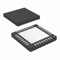
LMX2531LQ1570E/NOPB National Semiconductor, LMX2531LQ1570E/NOPB Datasheet - Page 28

LMX2531LQ1570E/NOPB
Manufacturer Part Number
LMX2531LQ1570E/NOPB
Description
IC PLL FREQ SYNTH W/VCO 36-LLP
Manufacturer
National Semiconductor
Series
PowerWise®r
Type
Clock/Frequency Synthesizer (RF)r
Datasheet
1.LMX2531LQ1778ENOPB.pdf
(36 pages)
Specifications of LMX2531LQ1570E/NOPB
Pll
Yes
Input
Clock
Output
CMOS
Number Of Circuits
1
Ratio - Input:output
2:2
Differential - Input:output
No/No
Frequency - Max
1.636GHz
Divider/multiplier
Yes/No
Voltage - Supply
2.8 V ~ 3.2 V
Operating Temperature
-40°C ~ 85°C
Mounting Type
Surface Mount
Package / Case
36-LLP
Frequency-max
1.6GHz
Lead Free Status / RoHS Status
Lead free / RoHS Compliant
Other names
LMX2531LQ1570ETR
2.6 REGISTER R5
2.6.1 EN_PLL -- Enable Bit for PLL
When this bit is set to 1 (default), the PLL is powered up, otherwise, it is powered down.
2.6.2 EN_VCO -- Enable Bit for the VCO
When this bit is set to 1 (default), the VCO is powered up, otherwise, it is powered down.
2.6.3 EN_OSC -- Enable Bit for the Oscillator Inverter
When this bit is set to 1 (default), the reference oscillator is powered up, otherwise it is powered down.
2.6.4 EN_VCOLDO -- Enable Bit for the VCO LDO
When this bit is set to 1 (default), the VCO LDO is powered up, otherwise it is powered down.
2.6.5 EN_PLLLDO1 -- Enable Bit for the PLL LDO 1
When this bit is set to 1 (default), the PLL LDO 1 is powered up, otherwise it is powered down.
2.6.6 EN_PLLLDO2 -- Enable Bit for the PLL LDO 2
When this bit is set to 1 (default), the PLL LDO 2 is powered up, otherwise it is powered down.
2.6.7 EN_DIGLDO -- Enable Bit for the digital LDO
When this bit is set to 1 (default), the Digital LDO is powered up, otherwise it is powered down.
2.6.8 REG_RST -- RESETS ALL REGISTERS TO DEFAULT SETTINGS
This bit needs to be programmed three times to initialize the part. When this bit is set to one, all registers are set to default mode,
and the part is powered down. The second time the R5 register is programmed with REG_RST=0, the register reset is released
and the default states are still in the registers. However, since the default states for the blocks and LDOs is powered off, it is
therefore necessary to program R5 a third time so that all the LDOs and blocks can be programmed to a power up state. When
this bit is set to 1, all registers are set to the default modes, but part is powered down. For normal operation, this bit is set to 0.
Note that once this initialization is done, it is not necessary to do this again unless power is removed from the device.
www.national.com
28


