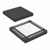
LMX2531LQ1570E/NOPB National Semiconductor, LMX2531LQ1570E/NOPB Datasheet - Page 5

LMX2531LQ1570E/NOPB
Manufacturer Part Number
LMX2531LQ1570E/NOPB
Description
IC PLL FREQ SYNTH W/VCO 36-LLP
Manufacturer
National Semiconductor
Series
PowerWise®r
Type
Clock/Frequency Synthesizer (RF)r
Datasheet
1.LMX2531LQ1778ENOPB.pdf
(36 pages)
Specifications of LMX2531LQ1570E/NOPB
Pll
Yes
Input
Clock
Output
CMOS
Number Of Circuits
1
Ratio - Input:output
2:2
Differential - Input:output
No/No
Frequency - Max
1.636GHz
Divider/multiplier
Yes/No
Voltage - Supply
2.8 V ~ 3.2 V
Operating Temperature
-40°C ~ 85°C
Mounting Type
Surface Mount
Package / Case
36-LLP
Frequency-max
1.6GHz
Lead Free Status / RoHS Status
Lead free / RoHS Compliant
Other names
LMX2531LQ1570ETR
VregPLL1
VregPLL2
VregVCO
VrefVCO
VregDIG There is not really any reason to use any other values than the recommended value of 10 nF
VccVCO
VccBUF
VccDIG
VccPLL
Connection Diagram
Pin(s)
DATA
CLK
LE
These pins are inputs to voltage regulators. Because the LMX2531 contains internal regulators, the power supply noise
rejection is very good and capacitors at this pin are not critical. An RC filter can be used to reduce supply noise, but if the
capacitor is too large and is placed too close to these pins, they can sometimes cause phase noise degradation in the 100
- 300 kHz offset range. Recommended values are from open to 1 μF. The series resistors serve to filter power supply noise
and isolate these pins from large capacitances.
If the VrefVCO capacitor is changed, it is recommended to keep this capacitor between 1/100 and 1/1000 of the value of
the VregVCO capacitor.
Because this pin is the output of a regulator, there are stability concerns if there is not sufficient series resistance. For
ceramic capacitors, the ESR (Equivalent Series Resistance) is too low, and it is recommended that a series resistance of
1 - 3.3Ω is necessary. If there is insufficient ESR, then there may be degradation in the phase noise, especially in the 100
- 300 kHz offset. Recommended values are from 1 μF to 10 μF.
The choice of the capacitor value at this pin involves a trade-off between integer spurs and phase noise in the 100 - 300
kHz offset range. Using a series resistor of about 220 mΩ in series with a capacitance that has an impedance of about 150
mΩ at the phase detector frequency seems to give an optimal trade-off. For instance, if the phase detector frequency is
2.5 MHz, then make this series capacitor 470 nF. If the phase detector frequency is 10 MHz, make this capacitance about
100 nF.
Since the maximum voltage on these pins is less than the minimum Vcc voltage, level shifting may be required if the output
voltage of the microcontroller is too high. This can be accomplished with a resistive divider.
Application Information
5
20101111
www.national.com


