1469054-1 TE Connectivity, 1469054-1 Datasheet - Page 4
1469054-1
Manufacturer Part Number
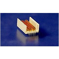
1469054-1
Description
HM-ZD 2PR HDR SELECT LOAD
Manufacturer
TE Connectivity
Specifications of 1469054-1
Product Type
Connector
Connector Type
Header
Pcb Mounting Orientation
Vertical
Shield Material
Phosphor bronze
Module Length (mm [in])
24.90 [0.980]
Interface Type
HM-Zd
Termination Method
Press Fit
Termination End Plating
Tin-Lead over Nickel
Card Slot Pitch (mm [in])
20.3 [0.8]
Columns Per Connector
10
Centerline (mm [in])
2.50 [0.098]
Selectively Loaded
Yes
Number Of Positions
32
Contact Type
Pin
Contact Termination Type
Through Hole
Contact Configuration
ACTION PIN Post
Feedthrough Post Length (mm [in])
2.50 [0.098]
Contact Mating Area Length (mm [in])
6.35 [0.250]
Contact Base Material
Phosphor Bronze
Housing Material
Polyester GF
Number Of Pairs Per Column
2
Number Of Pairs Per Connector
20
Sequenced Pins
Yes (See Drawing)
Advancedtca Specified Product
No
Rohs/elv Compliance
RoHS compliant, ELV compliant
Lead Free Solder Processes
Not relevant for lead free process
Rohs/elv Compliance History
Always was RoHS compliant


Rev C
Com pliant pin insertion force.
Com pliant pin retention force.
Minute disturbance.
Receptacle cover retention.
Therm al shock.
Hum idity-tem perature cycling.
Tem perature life.
Mixed flowing gas.
Dust contam ination.
NOTE
Test Description
Shall meet visual requirements, show no physical damage, and meet requirements of additional
tests as specified in the Product Qualification and Requalification Test Sequence shown in Figure
2.
44.5 N [10 lbf] m axim um average
per pin.
4.4 N [1 lbf] m inim um average per
pin.
See Note.
111.25 N [25 lbf] m inim um per 25
m m [.984 in] long m odule.
See Note.
See Note.
See Note.
See Note.
See Note.
ENVIRONMENTAL
Figure 1 (end)
Requirem ent
TE Spec 109-41.
Measure force necessary to seat
pins into a printed circuit board at a
m axim um rate of 12.7 m m [.5 in]
per m inute.
TE Spec 109-30.
Measure force necessary to unseat
pins from a printed circuit board at
a m axim um rate of 12.7 m m [.5 in]
per m inute.
Unm ate and m ate each connector
pair a distance of approxim ately 0.1
m m [.004 in].
Measure force necessary to
rem ove receptacle front cover from
chicklet at a m axim um rate of 5.08
m m [.2 in] per m inute. Connectors
are to be inserted into the PCB's.
EIA-364-32, Test Condition II.
Subject m ated specim ens to 5
cycles between -65 and 105°C.
EIA-364-31, Method III.
Subject specim ens to 50 cycles (50
days) between 5 and 85°C at 80 to
100% RH.
EIA-364-17, Method A, Test
Condition 4, Test Tim e Condition D.
Subject m ated specim ens to 105°C
for 1000 hours.
EIA-364-65, Class IIIA.
Subject m ated and unm ated
specim ens to environm ental Class
IIIA for 20 days total.
EIA-364-91.Subject unm ated
specim ens to dust contam ination
#1 for 1 hour. Air flow shall be 360
cfm .
Procedure
108-2055
4 of 8
Related parts for 1469054-1
Image
Part Number
Description
Manufacturer
Datasheet
Request
R


Part Number:
Description:
High Speed / Modular Connectors 30P HEADER ASSY
Manufacturer:
TE Connectivity
Datasheet:

Part Number:
Description:
High Speed / Modular Connectors REC 6X005P R/A LT B-PLANE HS3
Manufacturer:
TE Connectivity
Datasheet:

Part Number:
Description:
High Speed / Modular Connectors 2MM HM RCPT 50P R/A AU
Manufacturer:
TE Connectivity
Datasheet:

Part Number:
Description:
High Speed / Modular Connectors 2MM HM RCPT 50P R/A AU
Manufacturer:
TE Connectivity
Datasheet:


Part Number:
Description:
Manufacturer:
TE Connectivity
Datasheet:


Part Number:
Description:
Manufacturer:
TE Connectivity
Datasheet:

Part Number:
Description:
Manufacturer:
TE Connectivity
Datasheet:

Part Number:
Description:
Manufacturer:
TE Connectivity
Datasheet: