1469054-1 TE Connectivity, 1469054-1 Datasheet - Page 5
1469054-1
Manufacturer Part Number
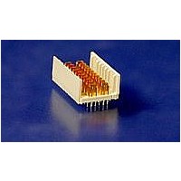
1469054-1
Description
HM-ZD 2PR HDR SELECT LOAD
Manufacturer
TE Connectivity
Specifications of 1469054-1
Product Type
Connector
Connector Type
Header
Pcb Mounting Orientation
Vertical
Shield Material
Phosphor bronze
Module Length (mm [in])
24.90 [0.980]
Interface Type
HM-Zd
Termination Method
Press Fit
Termination End Plating
Tin-Lead over Nickel
Card Slot Pitch (mm [in])
20.3 [0.8]
Columns Per Connector
10
Centerline (mm [in])
2.50 [0.098]
Selectively Loaded
Yes
Number Of Positions
32
Contact Type
Pin
Contact Termination Type
Through Hole
Contact Configuration
ACTION PIN Post
Feedthrough Post Length (mm [in])
2.50 [0.098]
Contact Mating Area Length (mm [in])
6.35 [0.250]
Contact Base Material
Phosphor Bronze
Housing Material
Polyester GF
Number Of Pairs Per Column
2
Number Of Pairs Per Connector
20
Sequenced Pins
Yes (See Drawing)
Advancedtca Specified Product
No
Rohs/elv Compliance
RoHS compliant, ELV compliant
Lead Free Solder Processes
Not relevant for lead free process
Rohs/elv Compliance History
Always was RoHS compliant


3.6.
Rev C
Initial examination of product
Low level contact resistance
Low level compliant pin resistance
Insulation resistance
Withstanding voltage
Temperature rise vs current
Vibration
Mechanical shock
Durability
Mating force
Unmating force
Compliant pin insertion force
Compliant pin retention force
Minute disturbance
Receptacle cover retention
Thermal shock
Humidity-temperature cycling
Temperature life
Mixed flowing gas (mated)
Mixed flowing gas (unmated)
Dust contamination
Final examination of product
Product Qualification and Requalification Test Sequence
A.
NOTE
Two and Four Pair HM-Zd Connectors (right angle receptacle, vertical header)
Test or Examination
(a)
(b)
(c)
(d)
(e)
See paragraph 4.1.A.
Numbers indicate sequence in which tests are performed.
Perform 10 durability cycles prior to initial measurement.
Perform 125 durability cycles before, and 125 durability cycles after mixed flowing gas
testing.
Exposure interval of 5 days.
4,7,9,11,13 5,8,10,12,14 5(c),8 4,6,8,10,12,14,16,18
2,15
3,16
5,14
10
12
17
1
1
6
8
Figure 2A
3,18
4,19
6,17
15
16
20
11
13
21
2
1
7
2
9
Test Sequence (b)
Test Group (a)
3,10
4,11
6,9
12
13
3
1
2
7
11(e),13(e)
5(d),17(d)
7(e),9(e)
2,20
19
15
21
4
1
3
5
1
2
3
108-2055
6
1
2
3
5 of 8
Related parts for 1469054-1
Image
Part Number
Description
Manufacturer
Datasheet
Request
R


Part Number:
Description:
High Speed / Modular Connectors 30P HEADER ASSY
Manufacturer:
TE Connectivity
Datasheet:

Part Number:
Description:
High Speed / Modular Connectors REC 6X005P R/A LT B-PLANE HS3
Manufacturer:
TE Connectivity
Datasheet:

Part Number:
Description:
High Speed / Modular Connectors 2MM HM RCPT 50P R/A AU
Manufacturer:
TE Connectivity
Datasheet:

Part Number:
Description:
High Speed / Modular Connectors 2MM HM RCPT 50P R/A AU
Manufacturer:
TE Connectivity
Datasheet:


Part Number:
Description:
Manufacturer:
TE Connectivity
Datasheet:


Part Number:
Description:
Manufacturer:
TE Connectivity
Datasheet:

Part Number:
Description:
Manufacturer:
TE Connectivity
Datasheet:

Part Number:
Description:
Manufacturer:
TE Connectivity
Datasheet: