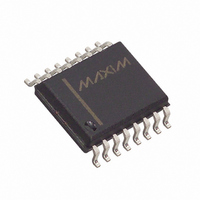
DS3231SN# Maxim Integrated Products, DS3231SN# Datasheet - Page 11

DS3231SN#
Manufacturer Part Number
DS3231SN#
Description
IC RTC W/TCXO 16-SOIC
Manufacturer
Maxim Integrated Products
Type
Clock/Calendar/TCXO/Crystalr
Datasheet
1.DS3231S.pdf
(20 pages)
Specifications of DS3231SN#
Time Format
HH:MM:SS (12/24 hr)
Date Format
YY-MM-DD-dd
Interface
I²C, 2-Wire Serial
Voltage - Supply
2.3 V ~ 5.5 V
Operating Temperature
-40°C ~ 85°C
Mounting Type
Surface Mount
Package / Case
16-SOIC (0.300", 7.5mm Width)
Function
Clock/Calendar/Battery Backup
Supply Voltage (max)
5.5 V
Supply Voltage (min)
2.3 V
Maximum Operating Temperature
+ 85 C
Minimum Operating Temperature
- 40 C
Mounting Style
SMD/SMT
Rtc Bus Interface
Serial (I2C)
Lead Free Status / RoHS Status
Lead free / RoHS Compliant
Memory Size
-
Lead Free Status / Rohs Status
Lead free / RoHS Compliant
Available stocks
Company
Part Number
Manufacturer
Quantity
Price
Figure 1 shows the address map for the DS3231 time-
keeping registers. During a multibyte access, when the
address pointer reaches the end of the register space
(12h), it wraps around to location 00h. On an I
START or address pointer incrementing to location 00h,
the current time is transferred to a second set of regis-
ters. The time information is read from these secondary
registers, while the clock may continue to run. This
eliminates the need to reread the registers in case the
main registers update during a read.
The I
V
to the DS3231 resets because of a loss of V
Figure 1. Timekeeping Registers
Note: Unless otherwise specified, the registers’ state is not defined when power is first applied.
A D D R ESS
BAT
0Ah
0Bh
0Ch
0Dh
00h
01h
02h
03h
04h
05h
06h
07h
08h
09h
0Eh
0Fh
10h
11h
12h
2
is at a valid level. If a microcontroller connected
C interface is accessible whenever either V
Century
A1M1
A1M2
A1M3
A1M4
A2M2
A2M3
A2M4
EOSC
DATA
BIT 7
SIGN
SIGN
MSB
OSF
0
0
0
0
0
BBSQW
DY/DT
DY/DT
DATA
DATA
DATA
12/24
12/24
12/24
BIT 6
0
0
0
0
10 Year
10 Seconds
10 Seconds
10 Minutes
10 Minutes
10 Minutes
20 Hour
20 Hour
20 Hour
AM/PM
AM/PM
AM/PM
CONV
Extremely Accurate I
DATA
DATA
BIT 5
0
0
0
0
I
Address Map
10 Date
10 Date
10 Date
2
C Interface
____________________________________________________________________
10 Month
10 Hour
10 Hour
10 Hour
DATA
DATA
BIT 4
RS2
0
0
0
CC
or other
EN32kHz
CC
DATA
DATA
BIT 3
RS1
2
0
0
or
C
INTCN
event, it is possible that the microcontroller and
DS3231 I
chronized, e.g., the microcontroller resets while read-
ing data from the DS3231. When the microcontroller
resets, the DS3231 I
known state by toggling SCL until SDA is observed to
be at a high level. At that point the microcontroller
should pull SDA low while SCL is high, generating a
START condition.
The time and calendar information is obtained by read-
ing the appropriate register bytes. Figure 1 illustrates
the RTC registers. The time and calendar data are set
or initialized by writing the appropriate register bytes.
The contents of the time and calendar registers are in
DATA
DATA
BIT 2
BSY
Seconds
Seconds
Minutes
Minutes
Minutes
0
Month
Hour
Hour
Hour
Date
Year
Date
Date
Day
Day
DATA
DATA
BIT 1
A2IE
A2F
Day
2
0
C communications could become unsyn-
RTC/TCXO/Crystal
DATA
DATA
BIT 0
A1IE
LSB
A1F
0
2
C interface may be placed into a
2
Alarm 1 Seconds
Clock and Calendar
Alarm 1 Minutes
Alarm 2 Minutes
C-Integrated
Alarm 1 Hours
Alarm 2 Hours
Control/Status
MSB of Temp
Alarm 1 Date
Alarm 2 Date
LSB of Temp
Aging Offset
Alarm 1 Day
Alarm 2 Day
FUNCTION
Seconds
Minutes
Century
Control
Month/
Hours
Date
Year
Day
1–12 + AM/PM
1–12 + AM/PM
1–12 + AM/PM
RANGE
01–12 +
Century
00–59
00–59
00–23
01–31
00–99
00–59
00–59
00–23
00–59
00–23
1–31
1–31
1–7
1–7
1–7
—
—
—
—
—
11


