ISL12024IRTCZ-T Intersil, ISL12024IRTCZ-T Datasheet - Page 11
ISL12024IRTCZ-T
Manufacturer Part Number
ISL12024IRTCZ-T
Description
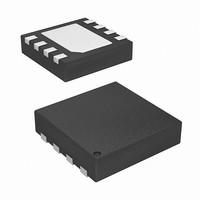
IC RTC/CALENDER 64BIT 8-TDFN
Manufacturer
Intersil
Type
Clock/Calendar/EEPROMr
Datasheet
1.ISL12024IRTCZ-T.pdf
(24 pages)
Specifications of ISL12024IRTCZ-T
Memory Size
4K (512 x 8)
Time Format
HH:MM:SS (12/24 hr)
Date Format
YY-MM-DD-dd
Interface
I²C, 2-Wire Serial
Voltage - Supply
2.7 V ~ 5.5 V
Operating Temperature
-40°C ~ 85°C
Mounting Type
Surface Mount
Package / Case
8-TDFN
Lead Free Status / RoHS Status
Lead free / RoHS Compliant


Alarm Registers (Non-Volatile)
Alarm0 and Alarm1
The alarm register bytes are set up identical to the RTC
register bytes, except that the MSB of each byte functions as
an enable bit (enable = “1”). These enable bits specify which
alarm registers (seconds, minutes, etc.) are used to make
the comparison. Note that there is no alarm byte for year.
The alarm function works as a comparison between the
alarm registers and the RTC registers. As the RTC
advances, the alarm will be triggered once a match occurs
between the alarm registers and the RTC registers. Any one
alarm register, multiple registers, or all registers can be
enabled for a match. See “Device Operation” on page 12
and “Application Section” on page 20 for more information.
Control Registers (Non-Volatile)
The Control Bits and Registers described in the following are
non-volatile.
BL Register
BP2, BP1, BP0 - Block Protect Bits
The Block Protect Bits, BP2, BP1 and BP0, determine which
blocks of the array are write protected. A write to a protected
block of memory is ignored. The block protect bits will
prevent write operations to one of eight segments of the
array. The partitions are described in Table 3.
INT Register: Interrupt Control and
Frequency Output Register
IM, AL1E, AL0E - Interrupt Control and Status Bits
There are two Interrupt Control bits; Alarm 1 Interrupt Enable
(AL1E) and Alarm 0 Interrupt Enable (AL0E) to specifically
enable or disable the alarm interrupt signal output
(IRQ/F
AL1E or AL0E or both bits are set to ‘1’ and both the FO1
and FO0 bits are set to 0 (F
0
0
0
0
1
1
1
1
OUT
0
0
1
1
0
0
1
1
). The interrupts are enabled when either the
0
1
0
1
0
1
0
1
PROTECTED ADDRESSES
ISL12024IRTCZ
None (Default)
180
100
000
000
000
000
000
TABLE 3.
OUT
h
h
h
h
h
h
h
11
– 1FF
– 1FF
– 1FF
– 03F
– 07F
– 0FF
– 1FF
disabled).
h
h
h
h
h
h
h
ARRAY LOCK
First 16 Pages
First 4 Pages
First 8 Pages
Upper 1/4
Upper 1/2
Full Array
Full Array
None
ISL12024IRTCZ
The IM bit enables the pulsed interrupt mode. To enter this
mode, the AL0E or AL1E bits are set to “1”, and the IM bit to
“1”. The IRQ/F
alarm occurs. This means that once the interrupt mode
alarm is set, it will continue to alarm for each occurring
match of the alarm and present time. This mode is
convenient for hourly or daily hardware interrupts in
microcontroller applications such as security cameras or
utility meter reading.
In this case both Alarms are enabled.
FO1, FO0 - Programmable Frequency Output Bits
These are two output control bits. They select one of three
divisions of the internal oscillator, that is applied to the
IRQ/F
this output. When using this function, the Alarm output
function is disabled.FO1 and FO0 are set to “01” for
32.768kHz output at power-up.
Oscillator Compensation Registers
There are two trimming options.
• ATR. Analog Trimming Register
• DTR. Digital Trimming Register
These registers are non-volatile. The combination of analog
and digital trimming can give up to -64ppm to +110 ppm of
total adjustment.
ATR Register - ATR5, ATR4, ATR3, ATR2, ATR1,
ATR0: Analog Trimming Register
Six analog trimming bits, ATR0 to ATR5, are provided in
order to adjust the on-chip load capacitance value for
frequency compensation of the RTC. Each bit has a different
weight for capacitance adjustment. For example, using a
Citizen CFS-206 crystal with different ATR bit combinations
provides an estimated ppm adjustment range from -34ppm
to +80ppm to the nominal frequency compensation.
The effective on-chip series load capacitance, C
ranges from 4.5pF to 20.25pF with a mid-scale value of
12.5pF (default). C
controlled capacitors, C
and X2 pins to ground (see Figure 8). The value of C
C
C X
X2
FO1
TABLE 4. PROGRAMMABLE FREQUENCY OUTPUT BITS
0
0
1
1
=
is given Equation 1:
(
OUT
16 b5
⋅
FO0
output pin. Table 4 shows the selection bits for
0
1
0
1
+
8 b4
OUT
⋅
LOAD
+
output will now be pulsed each time an
4 b3
⋅
X1
Alarm output (F
is changed via two digitally
+
32.768kHz (default setting)
and C
2 b2
OUTPUT FREQUENCY
⋅
+
X2
1 b1
4096Hz
⋅
, connected from the X1
1Hz
+
OUT
0.5 b0
⋅
disabled)
+
9
LOAD
)pF
August 8, 2008
X1
,
FN6749.0
(EQ. 1)
and
Related parts for ISL12024IRTCZ-T
Image
Part Number
Description
Manufacturer
Datasheet
Request
R

Part Number:
Description:
Real-Time Clock/Calendar
Manufacturer:
Intersil Corporation
Datasheet:
Part Number:
Description:
Intersil Corporation [CMOS Serial Controller Interface]
Manufacturer:
Intersil Corporation
Datasheet:
Part Number:
Description:
Manufacturer:
Intersil Corporation
Datasheet:
Part Number:
Description:
357-036-542-201 CARDEDGE 36POS DL .156 BLK LOPRO
Manufacturer:
Intersil Corporation
Datasheet:
Part Number:
Description:
1024-Word x 4-Bit LSI Static RAM
Manufacturer:
Intersil Corporation
Datasheet:
Part Number:
Description:
General Purpose NPN Transistor Arrays FN341.4
Manufacturer:
Intersil Corporation
Datasheet:
Part Number:
Description:
CMOS 16-Bit Microprocessor
Manufacturer:
Intersil Corporation
Datasheet:
Part Number:
Description:
Manufacturer:
Intersil Corporation
Datasheet:
Part Number:
Description:
Manufacturer:
Intersil Corporation
Datasheet:
Part Number:
Description:
Manufacturer:
Intersil Corporation
Datasheet:
Part Number:
Description:
Manufacturer:
Intersil Corporation
Datasheet:
Part Number:
Description:
CMOS 6-Bit Latch and Decoder Memory Interfaces
Manufacturer:
Intersil Corporation
Datasheet:
Part Number:
Description:
CA3046General Purpose NPN Transistor Arrays
Manufacturer:
Intersil Corporation
Datasheet:
Part Number:
Description:
Manufacturer:
Intersil Corporation
Datasheet:
Part Number:
Description:
TR909 DLC/FLC SLIC with Low Power Standby
Manufacturer:
Intersil Corporation
Datasheet: