2-487952-8 TE Connectivity, 2-487952-8 Datasheet

028 1MM FPC BTM HORZ

2-487952-8

Manufacturer Part Number
2-487952-8
Description
028 1MM FPC BTM HORZ
Manufacturer
TE Connectivity
Datasheets

Specifications of 2-487952-8

Termination Method To Pc Board
Surface Mount
Pcb Mounting Orientation
Right Angle
Pcb Mount Alignment
Without
Pcb Mount Retention
With
Actuator Type
Stuffer
Shrouded
Yes
Sealed
No
Strain Relief
Without
Contact Current Rating, Max (a)
1
Operating Voltage Reference
AC
Operating Voltage (vac)
200
Shielded
No
Tail Orientation
In-line
Profile Height (y-axis) (mm [in])
2.56 [0.1008]
Centerline (mm [in])
1.00 [0.039]
Number Of Positions
28
Selectively Loaded
No
Pcb Mount Retention Type
Solder Pads
Length (x-axis) (mm [in])
35.92 [1.4142]
Width (z-axis) (mm [in])
6.54 [0.2575]
Contact Plating, Mating Area, Material
Tin-Lead
Contact Plating, Mating Area, Thickness (µm [?in])
0.381 [15]
Tail Plating Material
Tin-Lead
Tail Plating, Thickness (µm [?in])
0.381 [15]
Contact Design
Single Beam
Housing Material
Liquid Crystal Polymer (LCP)
Contact Mating Location
Bottom
Flex Cable Thickness (mm [in])
0.3 [0.012]
Housing Color
Ivory
Rohs/elv Compliance
Not ELV/RoHS compliant
Lead Free Solder Processes
Reflow solder capable to 245°C, Reflow solder capable to 260°C
Circuit Identification Feature
With
Operating Temperature (°c [°f])
-40 – +85 [-40 – +185]
Zif/non-zif
ZIF
Contact Transmits (typical Application)
Signal (Data)
Pick And Place Cover
Without
Packaging Method
Tape & Reel
1.
1.1.
1.2.
2.
3.
3.1.
3.2.
3.3.
©2011 Tyco Electronics Corporation,
a TE Connectivity Ltd. Company
All Rights Reserved
TE logo is a trademark.
SCOPE
Content
This specification covers performance, tests and quality requirements for the TE 1 mm FPC connector.
This connector ranges in size from 4 to 30 positions. A single contact is produced with tails to provide
right angle surface mount connections to a printed circuit board. An actuator provides ZIF action and the
socket accepts FEC, FFC, or FPC. The 2 right angle versions of the socket mate with the exposed
traces of the cable facing up or down. Housing can be equipped with solder hold down tabs for both
right angle versions.
Qualification
When tests are performed on the subject product line, procedures specified in 109 Series Test
Specifications shall be used. All inspections shall be performed using the applicable inspection plan and
product drawing.
APPLICABLE DOCUMENTS
The following TE Connectivity (TE) documents form a part of this specification to the extent specified
herein. Unless otherwise specified, the latest edition of the document applies. In the event of conflict
between the requirements of this specification and the product drawing, the product drawing shall take
precedence. In the event of conflict between the requirements of this specification and the referenced
documents, this specification shall take precedence.
!
!
!
!
REQUIREMENTS
Design and Construction
Product shall be of the design, construction and physical dimensions specified on the applicable product
drawing.
Materials
!
!
!
!
Ratings
!
!
!
109-1: General Requirements for Test Specifications
109 Series: Test Specifications as indicated in Figure 1
114-1072: Application Specification
501-278: Qualification Test Report
Actuator: Glass reinforced nylon (PPA), UL94V-0 or glass reinforced PPS UL94V-0
Board mount: Phosphor bronze, tin plating
Contact: Phosphor bronze, tin-lead over nickel plating
Housing: Glass reinforced polyester (LCP), UL94V-0
Voltage: 200 volts AC (rms)
Current: Signal application only, 1 ampere maximum for single circuit
Temperature: -40 to 85° C
| Indicates change
*Trademark
Product
Specification
Connector, FPC, 1 mm
For latest revision, visit our website at www.te.com/documents.
For Regional Customer Service, visit our website at www.te.com
Other products, logos, and company names might be trademarks of their respective owners.
108-1393
11Mar11 Rev C
1 of 6
LOC B

Related parts for 2-487952-8

2-487952-8 Summary of contents

Page 1

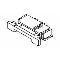
... An actuator provides ZIF action and the socket accepts FEC, FFC, or FPC. The 2 right angle versions of the socket mate with the exposed traces of the cable facing up or down. Housing can be equipped with solder hold down tabs for both right angle versions ...

Page 2

... Dielectric withstanding voltage. Solderability. Vibration, random. Physical shock. Durability. Rev C Requirement Meets requirements of product drawing and AMP Spec 114-1072. ELECTRICAL ∆R 10 milliohms maximum. 1000 megohms minimum. 500 volts AC at sea level. MECHANICAL Immerse contact tails to within .005 inch of housing. Dipped area shall have minimum of 95% solder coverage ...

Page 3

... Contact retention. Thermal shock. Humidity-temperature cycling. Temperature life. Shall meet visual requirements, show no physical damage and shall meet the requirements of NOTE additional tests as specified in the Test Sequence in Figure 2. 3.6. Product Qualification and Requalification Test Sequence Test or Examination Examination of product Termination resistance ...

Page 4

... Samples shall be prepared in accordance with applicable Instruction Sheets and shall be selected at random from current production. All test groups shall consist of a minimum of 5 connectors. Test groups 1 and 2 shall be soldered to printed circuit boards. A minimum of 30 contacts from these test groups shall be randomly selected and tested. If available, test group 1 shall contain both minimum and maximum size connectors ...

Page 5

Rev C Figure 3 Termination Resistance Measurement Points 108-1393 ...

Page 6

Vibration & Mechanical Shock Mounting Fixture Rev C Figure 4 108-1393 ...

Related keywords