2-487952-8 TE Connectivity, 2-487952-8 Datasheet - Page 2
2-487952-8
Manufacturer Part Number
2-487952-8
Description
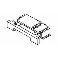
028 1MM FPC BTM HORZ
Manufacturer
TE Connectivity
Specifications of 2-487952-8
Termination Method To Pc Board
Surface Mount
Pcb Mounting Orientation
Right Angle
Pcb Mount Alignment
Without
Pcb Mount Retention
With
Actuator Type
Stuffer
Shrouded
Yes
Sealed
No
Strain Relief
Without
Contact Current Rating, Max (a)
1
Operating Voltage Reference
AC
Operating Voltage (vac)
200
Shielded
No
Tail Orientation
In-line
Profile Height (y-axis) (mm [in])
2.56 [0.1008]
Centerline (mm [in])
1.00 [0.039]
Number Of Positions
28
Selectively Loaded
No
Pcb Mount Retention Type
Solder Pads
Length (x-axis) (mm [in])
35.92 [1.4142]
Width (z-axis) (mm [in])
6.54 [0.2575]
Contact Plating, Mating Area, Material
Tin-Lead
Contact Plating, Mating Area, Thickness (µm [?in])
0.381 [15]
Tail Plating Material
Tin-Lead
Tail Plating, Thickness (µm [?in])
0.381 [15]
Contact Design
Single Beam
Housing Material
Liquid Crystal Polymer (LCP)
Contact Mating Location
Bottom
Flex Cable Thickness (mm [in])
0.3 [0.012]
Housing Color
Ivory
Rohs/elv Compliance
Not ELV/RoHS compliant
Lead Free Solder Processes
Reflow solder capable to 245°C, Reflow solder capable to 260°C
Circuit Identification Feature
With
Operating Temperature (°c [°f])
-40 – +85 [-40 – +185]
Zif/non-zif
ZIF
Contact Transmits (typical Application)
Signal (Data)
Pick And Place Cover
Without
Packaging Method
Tape & Reel


3.4.
3.5.
Rev C
Examination of product.
Termination resistance.
Insulation resistance.
Dielectric withstanding voltage.
Solderability.
Vibration, random.
Physical shock.
Durability.
Performance and Test Description
Product is designed to meet the electrical, mechanical and environmental performance requirements
specified in Figure 1. Unless otherwise specified, all tests shall be performed at ambient environmental
conditions per Test Specification 109-1.
Test Requirements and Procedures Summary
Test Description
Meets requirements of product
drawing and AMP Spec 114-1072.
∆R 10 milliohms maximum.
1000 megohms minimum.
500 volts AC at sea level.
Immerse contact tails to within .005
inch of housing. Dipped area shall
have minimum of 95% solder
coverage.
No discontinuities of 1 microsecond
or longer duration.
See Note.
No discontinuities of 1 microsecond
or longer duration.
See Note.
See Note.
Figure 1 (continued)
MECHANICAL
ELECTRICAL
Requirement
Visual, dimensional and functional
per applicable quality inspection
plan.
TE 109-6-1.
Subject mated contacts assembled
in housing to 50 mv maximum open
circuit at 100 ma maximum.
See Figure 3.
TE Spec 109-28-4.
Test between adjacent contacts of
unmated and unmounted samples.
TE Spec 109-29-1.
Test between adjacent contacts of
unmated and unmounted samples.
TE Spec 109-11-5, Test Method B.
Subject contacts to solderability.
TE Spec 109-21-5.
Subject mated samples to 23.91
G's rms. 15 minutes in each of 3
mutually perpendicular planes.
See Figure 4.
TE Spec 109-26-9.
Subject mated samples to 100 G's
sawtooth shock pulses of 6
milliseconds duration. 3 shocks in
each direction applied along 3
mutually perpendicular planes, 18
total shocks.
See Figure 4.
TE Spec 109-27.
Manually mate and unmate
samples for 30 cycles.
Procedure
108-1393
2 of 6
Related parts for 2-487952-8
Image
Part Number
Description
Manufacturer
Datasheet
Request
R

Part Number:
Description:
Conn DIN 41612 M 48 POS 5.08mm Solder RA Thru-Hole
Manufacturer:
TE Connectivity
Datasheet:

Part Number:
Description:
48P.IEC-F MALE CONN
Manufacturer:
TE Connectivity
Datasheet:

Part Number:
Description:
V42254B2202C480=PC612 FEDERLEI
Manufacturer:
TE Connectivity
Datasheet:


Part Number:
Description:
T9AS1D22-48=RELAY,QC/PC,SEAL,P
Manufacturer:
Tyco Electronics
Datasheet:

Part Number:
Description:
Conn Shrouded Header HDR 4 POS 2.54mm Solder ST Thru-Hole
Manufacturer:
TE Connectivity
Datasheet:

Part Number:
Description:
Connector Accessories Jack Socket Assembly Kit Stainless Steel
Manufacturer:
TE Connectivity
Datasheet:

Part Number:
Description:
CT BOX HDR V SMT 4P O/TAPE BLA
Manufacturer:
TE Connectivity
Datasheet:

Part Number:
Description:
PLUG & SOCKET CONN, HEADER, 24POS, 4.2MM
Manufacturer:
TE Connectivity
Datasheet:

Part Number:
Description:
MOD-4 REC.CONT.SCP
Manufacturer:
TE Connectivity
Datasheet:

Part Number:
Description:
A/L UNIV HDR 20P VERT LG LAT BLUE
Manufacturer:
TE Connectivity
Datasheet:
Part Number:
Description:
WIRE-BOARD CONN RECEPTACLE 50POS, 2.54MM
Manufacturer:
TE Connectivity
Datasheet:

Part Number:
Description:
Manufacturer:
TE Connectivity
Datasheet:

Part Number:
Description:
Manufacturer:
TE Connectivity
Datasheet:
