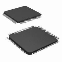
LM9833CCVJD/NOPB National Semiconductor, LM9833CCVJD/NOPB Datasheet - Page 24

LM9833CCVJD/NOPB
Manufacturer Part Number
LM9833CCVJD/NOPB
Description
IC USB IMAGE SCAN 48BIT 100-TOFP
Manufacturer
National Semiconductor
Datasheet
1.LM9833CCVJDNOPB.pdf
(42 pages)
Specifications of LM9833CCVJD/NOPB
Number Of Bits
16
Number Of Channels
3
Voltage - Supply, Analog
5V
Voltage - Supply, Digital
4.5 V ~ 5.5 V
Package / Case
100-TQFP, 100-VQFP
Lead Free Status / RoHS Status
Lead free / RoHS Compliant
Power (watts)
-
Other names
*LM9833CCVJD
*LM9833CCVJD/NOPB
LM9833CCVJD
*LM9833CCVJD/NOPB
LM9833CCVJD
Applications Information
the 2 bit DAC, shown in Figure 9.
4.2 Microstep Mode
Microstepping is a technique of driving the stepper motor with a
staircase approximation of a sine wave, as shown in Figure 10.
This technique maximizes the torque of a given motor, resulting in
a higher maximum speed. In addition, it increases the resolution
of the stepper motor. If a stepper motor moves 3.6° per full step,
microstepping can create positions inside the 3.6°: 1.8°, 0.9°, or
0.45°, for example. This increases the maximum vertical resolu-
tion of the scanner. Microstepping also results in quieter motor
movement.
The amplitude of the microstepped sine wave is controlled by the
output of the stepper motor DAC (Figure 11). The current in the
stepper motor winding is measured as a voltage across the sense
resistor, and the transistor drive signals are pulse width modu-
lated (PWM) to force the average current through the winding
equal to V
PWM, and Register 57 controls the minimum time the driver is on
every period. Register 57 should be set as short as possible, the
driver only needs to be on long enough to mask any transient
A
A
B
B
Starting from
a dead stop
Scanning
Stopped
Scan Mode
DAC
Figure 10: Bipolar Microstepping Waveform
/R
Figure 9: Full Step Current Control
SENSE
. Register 56 controls the frequency of the
0.484V for number of steps specified
in Kickstart Steps register (0-7). If
register is 0 there is no Kickstart
current-movement begins at 0.347V.
0.347V
0.133V for number of steps specified
in Hold Current Timeout register (1 -
31), 0V after time out.
DAC Voltage
1 microstep
(Continued)
24
noise generated by the driver transistor turning on.
Figure 12 shows the LM9833’s DAC voltages. The peak current
through the stepper motor winding will be 0.484V/R
table index is incremented every microstep (StepSize pixel peri-
ods).
4.3 Pause Behavior - Non-Reversing Mode
When the Full Steps to Reverse When Buffer is Full register is
0, the stepper motor simply stops moving when the Pause signal
is received, as shown in Figure 13. The line of data currently
being processed (section “a” in Figure 13) will continue to be pro-
cessed and stored in DRAM. Additional lines may be digitized
and stored as well, depending on the number programmed in the
Lines to Process After Pause Scan Signal register (Figure 14).
This value is different for different scanner designs and should be
empirically set to the value that minimizes the spatial distortion
created by the motor slowing down and stopping.
Microstep
DAC A
DAC B
Figure 11: Stepper Motor Waveform - LM9833 Signals
TR
Pulse
A
A
B
B
Index
Table
Figure 12: Microstepping Current Control
-0
-1
-2
-3
-4
0
1
2
3
4
Figure 13: Stepper Motor Stopping
A (B)
Scanning
0
1
1
1
1
0
0
0
0
0
Pause
Signal
a
A (B)
0
0
0
0
0
0
1
1
1
1
b
N/A
0.195V
0.347V
0.448V
0.484V
N/A
0.195V
0.347V
0.448V
0.484V
Voltage
DAC
c
www.national.com
SENSE
d
. The


